


8 - 44
–+
ELEC
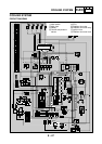
SIGNALING SYSTEM
EAS00753
YES
NO
YES
NO
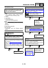
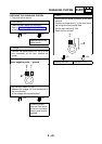
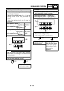
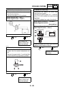
3. Starting circuit cut-off relay
• Disconnect the starting circuit cut-off relay
from the wire harness.
• Connect the pocket tester (
Ω
×
1) to the
starting circuit cut-off relay terminals as
shown.
• Check the starting circuit cut-off relay for
continuity.
Tester positive probe
→
sky blue
1
Tester negative probe
→
light green
2
Continu-
ity
Tester positive probe
→
light green
2
Tester negative probe
→
sky blue
1
No conti-
nuity
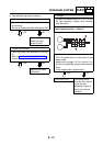
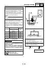
NOTE:
@
When you switch the positive and negative
tester probes, the readings in the above chart
will be reversed.
@
• Are the tester readings correct?
Replace the starting
circuit cut-off relay.
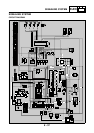
Lg
L/G
L/Y
Sb
B/Y
B
R/B
L/W
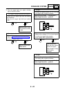
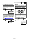
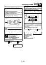
4. Voltage
• Connect the pocket tester (DC 20 V) to the
meter assembly coupler as shown.
Tester positive probe
→
brown/red
1
Tester negative probe
→
light green
2
• Set the main switch to “ON”.
• Measure the voltage (12 V).
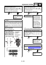
• Is the voltage within specification?
Replace the wind-
shield drive unit.
The wiring circuit
from the main switch
to the meter assem-
bly coupler is faulty
and must be
repaired.
R/W
G/WY/L
Lg
Y
Ch
Dg
L
R/G
B/W
Br/R
W