


3.35
ENGINE
3
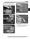
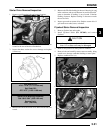
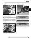
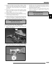
3. Turn the shaft until balancer counter weights clear the
crankshaft and remove the balancer shaft from the
crankcase.
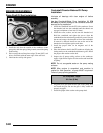
4. Inspect the balancer drive gear and pump shaft drive gear.
5. Replace the shaft if gear teeth are abnormally worn or
damaged.
6. Inspect the balancer shaft bearings.
NOTE: Due to extremely close tolerances and minimal
wear, the balancer shaft ball bearings must be inspected
visually and by feel. Look for signs of discoloration,
scoring or galling. Turn the inner race of each bearing.
The bearings should turn smoothly and quietly. The outer
race of each bearing should fit tightly in the crankcase.
The inner race should be firm with minimal side to side
movement and no detectable up and down movement.
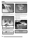
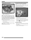
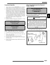
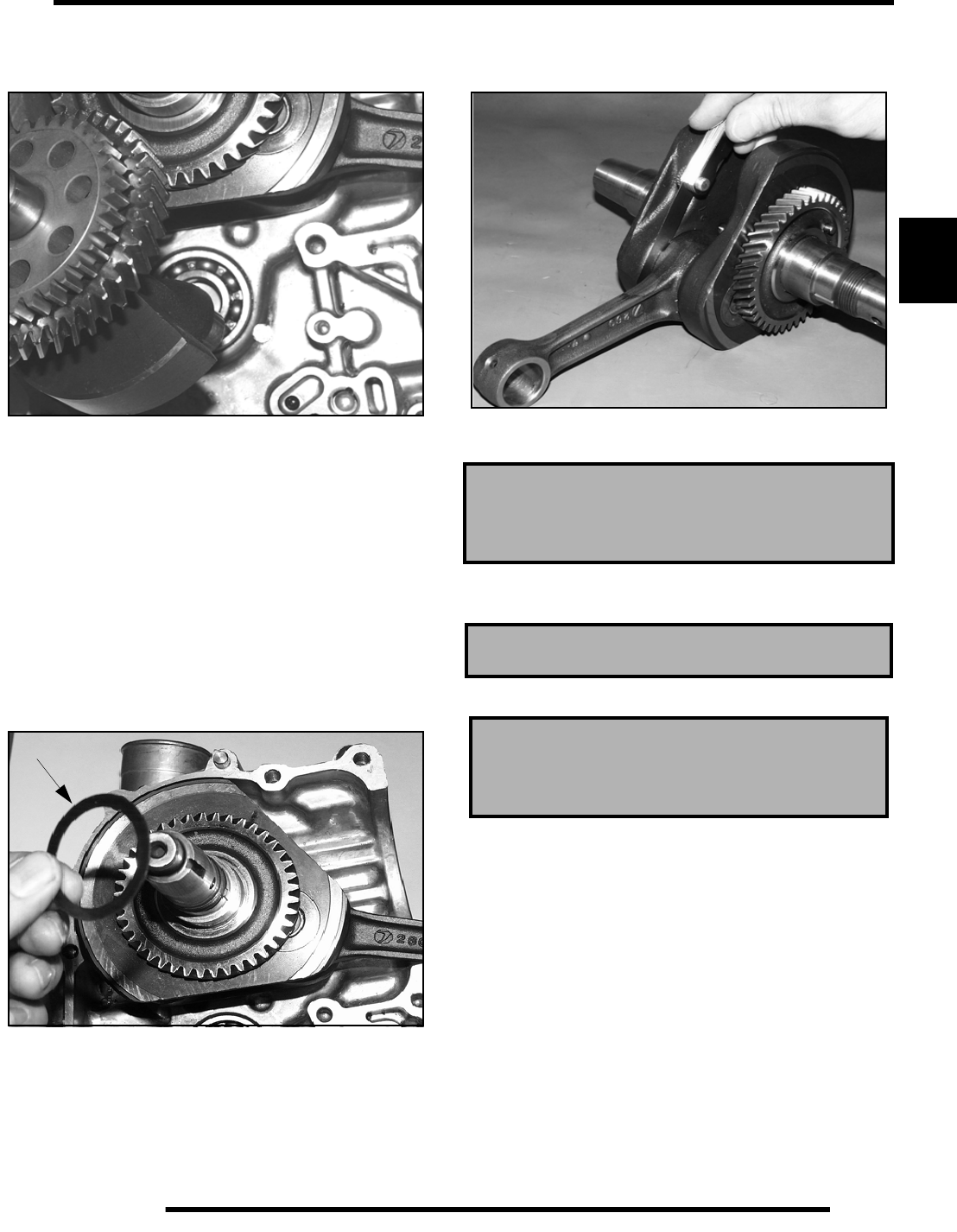
Crankshaft Removal/Inspection
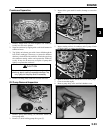
7. Remove the shim washer (A) from the crankshaft.
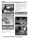
8. Support the PTO side crankcase and crankshaft; press the
crankshaft out. Be careful not to damage the crankcase
mating surface or connecting rod.
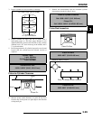
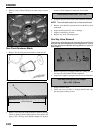
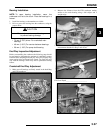
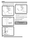
9. Use a feeler gauge to measure the connecting rod big end
side clearance.
10. Place the crankshaft in a truing stand or V-blocks and
measure the runout on both ends with a dial indicator.
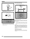
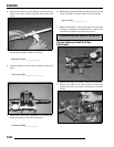
11. Measure the connecting rod big end radial clearance.
12. Inspect the crankshaft main bearing journals for scoring
and abnormal wear.
A
Connecting Rod Big End Side Clearance:
Std: .0039-.0256” (.1-.65 mm)
Limit: .0315” (.80 mm)
Max Runout: .0024” (.06 mm)
Big End Radial Clearance:
Std: .0004-.0015” (.011-.038 mm)
Limit: .0020” (.05 mm)