


6.17
CLUTCH SYSTEM
6
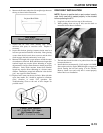
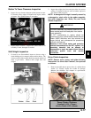
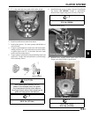
Button To Tower Clearance Inspection
1. Inspect for any clearance between spider button to tower.
If clearance exists, replace all buttons and inspect surface
of towers. See “Spider Removal” procedure.
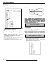
2. Inspect sheave surfaces. Replace the entire clutch as an
assembly if worn, damaged or cracked.
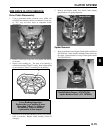
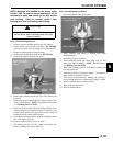
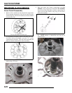
Shift Weight Inspection
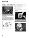
1. If clutch is not disassembled, inspect as shown, using a
clutch holding tool to compress the moveable sheave. The
contact surface of the weight should be smooth and free of
dents or gall marks. Remove shift weight bolts and
weights.
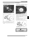
2. Inspect the weight pivot bore and pivot bolts for wear or
galling. If weights or bolts are worn or broken, replace in
sets of three with new bolts.
NOTE: A damaged shift weight is usually caused by
a damaged or stuck roller in the spider assembly.
See roller inspection, see “Roller, Pin, and Thrust
Washer Inspection”.
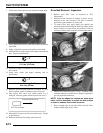
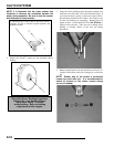
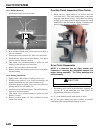
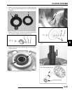
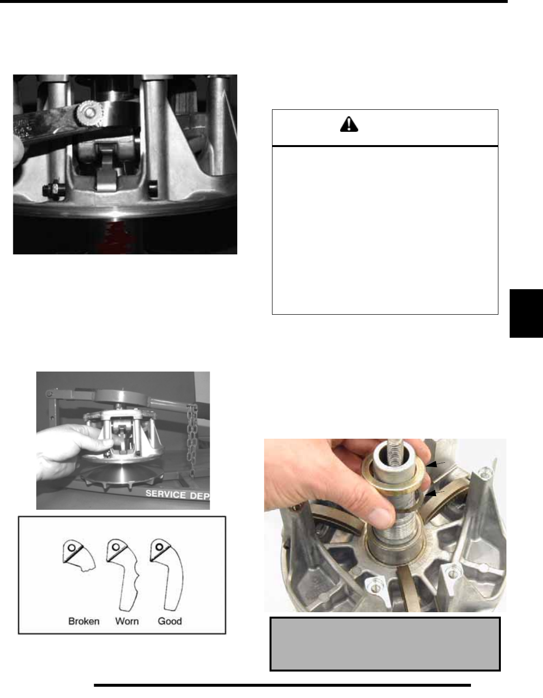
Drive Clutch Inspection
NOTE: Remove cover, spring, and spider following
instructions for drive clutch removal, then proceed
as follows:
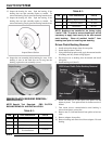
1. Remove moveable sheave spacer sleeve (1) and the thrust
washer (2). Visually inspect the washer for damage.
Measure the thickness and compare to specification.
Replace if worn or damaged.
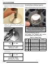
Button to Tower Clearance: .000-.001
WARNING
The clutch assembly is a precisely balanced unit.
Never replace parts with used parts from another
clutch assembly!
All PVT maintenance or repairs should be
performed only by a certified Polaris Master Service
Dealer (MSD) technician who has received the
proper training and understands the procedures
outlined in this manual.
Because of the critical nature and precision
balance incorporated into the PVT system, it is
absolutely essential that no attempt at
disassembly or repair be made without factory
authorized special tools and service
procedures.
Thrust Washer Thickness
Standard: .030, (.76mm)
Service Limit: .025, (.64mm)
1
2