


6.12
CLUTCH SYSTEM
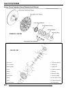
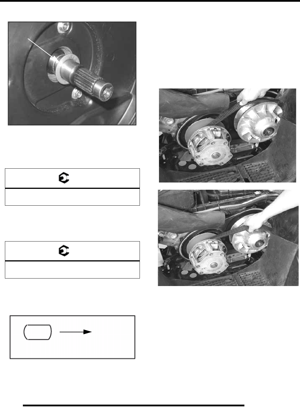
7. Install clutch offset spacer(s) on transmission input shaft.
8. Clean splines inside driven clutch and on the transmission
input shaft.
9. Apply a light film of grease to the splines on the shaft.
10. Install the driven clutch, washer, lock washer, and retaining
bolt. Torque to specification.
11. Clean end of taper on crankshaft and the taper bore inside
drive clutch.
12. Install drive clutch and torque retaining bolt to
specification.
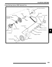
13. Reinstall drive belt noting direction of rotation. If a new
belt is installed, install so numbers can be easily read.
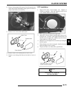
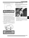
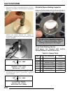
14. Only replace PVT outer cover rubber gasket if it is
damaged. Place the gasket with the narrow side out (C).
15. Reinstall PVT outer cover and secure with screws. Torque
to specification.
16. Reinstall cab/footwell assembly, panel and seat.
Drive Belt Removal / Inspection
1. Remove outer PVT cover as described in PVT
Disassembly.
2. Mark drive belt direction of rotation so that it can be
installed in the same direction. The belt is normally
positioned so part numbers are easily read.
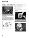
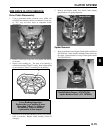
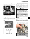
3. To remove drive belt, apply brake, pull upward and
rearward on belt while turning the back (moveable) driven
sheave clockwise to open driven clutch sheaves. Pull out
and down on belt to slip over the driven clutch outer sheave.
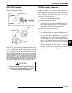
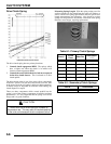
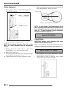
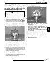
4. Measure belt width and replace if worn. Generally, belts
should be replaced if clutches can no longer be adjusted to
provide proper belt deflection.
NOTE: If the top edges are trimmed on some drive
belts, it will be necessary to project the side profiles
in order to measure from corner-to-corner.
5. Place a straight edge on each side of the drive belt. Place
another straight edge on top of belt.
= T
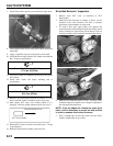
Driven Clutch Retaining Bolt Torque:
17 ft. lbs. (23.5 Nm)
= T
Drive Clutch Retaining Bolt Torque:
40 ft. lbs. (55 Nm)
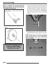
Offset Spacer
PVT Cover Gasket
Towards Outside Cover