


10.4
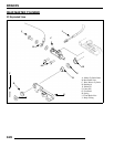
ELECTRICAL
Electrical Service Notes
Keep the following notes in mind when diagnosing an electrical
problem:
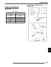
• Refer to wiring diagram for stator and electrical
component resistance specifications.
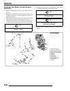
• When measuring resistance of a component that has a
resistance value under 10 Ohms, remember to subtract
meter lead resistance from the reading. Connect the
leads together and record the resistance. The resistance
of the component is equal to tested value minus the lead
resistance.
• Become familiar with the operation of your meter. Be
sure leads are in the proper jack for the test being
performed (i.e. 10Ajack for current readings). Refer to
the Owner’s manual included with your meter for more
information.
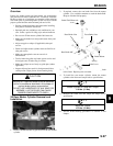
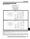
• Voltage, amperage, and resistance values included in
this manual are obtained with a Fluke
77 Digital
Multimeter (PV-43568). This meter is used for when
diagnosing electrical problems. Readings obtained with
other meters may differ.
• Pay attention to the prefix on the multimeter reading (K,
M, etc.) and the position of the decimal point.
• For resistance readings, isolate the component to be
tested. Disconnect it from the wiring harness or power
supply.
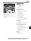
Troubleshooting
No Spark, Weak or Intermittent Spark
• Spark plug gap incorrect
• Fouled spark plug
• Faulty spark plug cap or poor connection to high
tension lead
• Related wiring loose, disconnected, shorted or corroded
• Engine stop switch or ignition switch faulty
• ETC switch misadjusted or faulty
• Wire harness or connections wet, corroded or broken
• Poor ignition coil ground
• Incorrect wiring after repair (inspect color coding in
connectors, etc.)
• Faulty ignition coil windings (measure resistance of
primary and secondary)
• Sheared flywheel key
• Flywheel Loose or damaged
• Excessive crankshaft runout - should not exceed .0024”
• Faulty ECM
• Faulty CPS
• Low Battery