


4.12
FUEL INJECTION
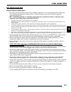
ELECTRONIC CONTROL MODULE
(ECM)
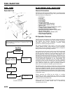
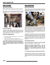
Operation Overview
The ECM is the brain or central processing computer of the
entire EFI fuel/ignition management system. During operation,
sensors continuously gather data which is relayed through the
wiring harness to input circuits within the ECM. Signals to the
ECM include: ignition (on/off), crankshaft position and speed
(RPM), throttle position, engine coolant temperature, air
temperature, intake manifold air pressure and battery voltage.
The ECM compares the input signals to the programmed maps
in its memory and determines the appropriate fuel and spark
requirements for the immediate operating conditions. The ECM
then sends output signals to set the injector duration and ignition
timing.
During operation, the ECM continually performs a diagnostic
check of itself, each of the sensors, and system performance. If
a fault is detected, the ECM turns on the Malfunction Indicator
Light (MIL) (Check Engine Light) on the speedometer and
stores the fault code in its fault memory. A technician can
access the stored fault codes manually using a “blink code”
diagnosis flashed out through the instrument cluster or using the
Digital Wrench Diagnostic Software. The ECM requires a
minimum of 7.0 volts to operate. The memory in the ECM is
operational the moment the battery cables are connected.
Depending on the significance or severity of the fault, normal
operation may continue, or a "Fail-Safe" operation may be
initiated. In the event a “Fail-Safe” mode occurs, a base fueling
table is used to determine the injector pulse width. This strategy
will not compensate for engine temperature, intake air
temperature, or altitude change, but instead operates based on
the latest valid information taken from those sensors.
To prevent engine over-speed and possible failure, an RPM-
limiting feature is programmed into the ECM. If the maximum
RPM limit (7000) is exceeded, the ECM will suppress the
ignition signal or injection signal. This process repeats itself in
rapid succession, limiting operation to the preset maximum.
Sportsman 500 EFI RPM Limit:
This EFI system utilizes 2 methods -
“Hard” Limit - Ignition suppression occurs when RPM peaks
rapidly:
• High: 7000 RPM
• Returns: 6900 RPM
“Soft” Limit - Injector suppression occurs when RPM reaches
peak gradually:
• High: 7000 RPM
• Returns: 6900 RPM
RPM limits may vary slightly under operating conditions.
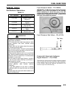
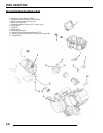
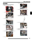
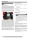
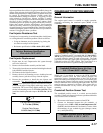
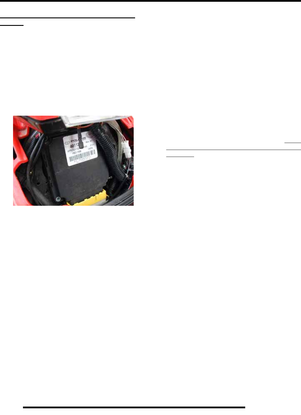
ECM Replacement
1. Remove the 2 retaining screws holding the ECM. NOTE:
Retain upper-left spacer located behind the ECM for re-
installation.
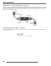
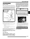
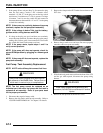
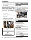
2. With the ignition turned off, disconnect the wire harness by
pulling the black slider away from the ECM. Once the slider
is fully extended, pull the connector from the ECM, using
great care not to damage the harness connector or locking
mechanism. NOTE: Should the black slider become
broken, replacement parts are available.
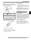
3. To install, reverse the procedures, DO NOT apply dielectric
grease to the connector, as it is a sealed connector. Install
the upper-left retaining screw spacer and screws. Tighten
screws to 10 in. lbs. (1.1 Nm).
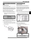
ECM Service
Never attempt to disassemble the ECM. It is sealed to prevent
damage to internal components. Warranty is void if the case is
opened or tampered with in any way.
All operating and control functions within the ECM are pre-set.
No internal servicing or readjustment may be performed. If a
problem is encountered, and you determine the ECM to be
faulty, contact the Polaris Service Department for specific
handling instructions. Do not replace the ECM without factory
authorization.
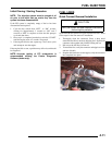
The relationship between the ECM and the throttle position
sensor (TPS) is very critical to proper system operation. If the
TPS is faulty, or the mounting position of the TPS is altered, the
TPS must be re-initialized.
For the purpose of troubleshooting, a known-good ECM from a
same-model Polaris 500 ATV EFI may be used without system
or engine component damage.
ECM