


3.24
ENGINE
3. Place cylinder head on cylinder head table. NOTE: Be sure
cylinder head is still at 212
o
F (100
o
C) before installing
new guides.
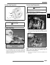
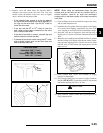
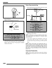
4. Place a new guide in the valve guide installation tool and
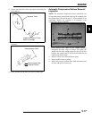
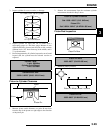
press guide in to proper depth. Check height of each guide
above the cylinder head (A). NOTE: The guide can also be
driven in to the proper depth. Inspect the guide closely for
cracks or damage if a driver is used.
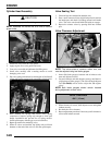
Reaming The Valve Guide
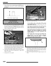
5. Allow cylinder head to cool to room temperature. Apply
cutting oil to the reamer. Guides should be reamed from the
valve spring side of the cylinder head. Ream each guide to
size by turning the reamer clockwise continually. Continue
to rotate reamer clockwise during removal of the tool.
6. Clean guides thoroughly with hot soapy water and a nylon
brush. Rinse and dry with compressed air. Apply clean
engine oil to guides.
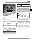
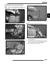
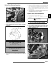
7. Install pilot into valve guide.
8. Apply cutting oil to valve seat and cutter.
9. Place 46
o
cutter on the pilot and make a light cut.
10. Inspect the cut area of the seat.
• If the contact area is less than 75% of the
circumference of the seat, rotate the pilot 180
o
and
make another light cut.
• If the cutter now contacts the uncut portion of the
seat, check the pilot. Look for burrs, nicks, or
runout. If the pilot is bent it must be replaced.
• If the contact area of the cutter is in the same
place, the valve guide is distorted from improper
installation and must be replaced. Be sure the
cylinder head is at the proper temperature and
replace the guide.
• If the contact area of the initial cut is greater than
75%, continue to cut the seat until all pits are
removed and a new seat surface is evident.
NOTE: Remove only the amount of material
necessary to repair the seat surface.
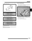
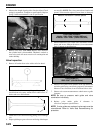
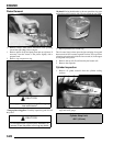
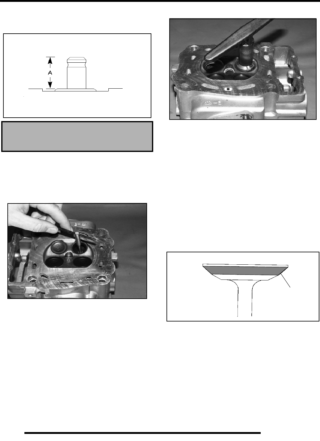
11. To check the contact area of the seat on the valve face, apply
a thin coating of Prussian Blue™ paste to the valve seat. If
using an interference angle (46
o
) apply black permanent
marker to the entire valve face (A).
12. Insert valve into guide and tap valve lightly into place a few
times.
Valve Guide Height:
.689-.709” (17.5-18.0 mm)
Valve Guide Installed Height
(A)