


3.26
ENGINE
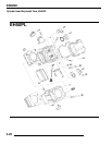
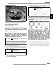
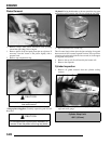
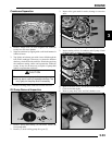
Cylinder Head Assembly
NOTE: Assemble the valves one at a time to maintain
proper order.
1. Install new valve seals on valve guides.
2. Apply engine oil to valve guides and seats.
3. Coat valve stem with molybdenum disulfide grease.
4. Install valve carefully with a rotating motion to avoid
damaging valve seal.
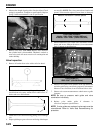
5. Dip valve spring and retainer in clean engine oil and install
spring with closely spaced coils toward the cylinder head.
6. Place retainer on springs and install valve spring
compressor. Compress spring only enough to allow split
keeper installation and prevent loss of spring tension.
Install split keepers with the gap even on both sides.
7. Repeat procedure for remaining valve.
8. When all valves are installed, tap lightly with soft faced
hammer on the end of the valves to seat the split keepers.
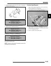
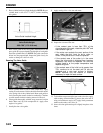
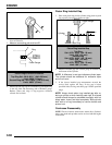
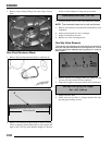
Valve Sealing Test
1. Clean and dry the combustion chamber area.
2. Pour a small amount of clean, high flash point solvent into
the intake port and check for leakage around each intake
valve. The valve seats should hold fluid with no seepage.
3. Repeat for exhaust valves by pouring fluid into exhaust
port.
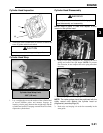
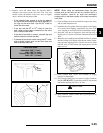
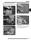
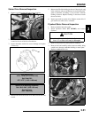
Valve Clearance Adjustment
NOTE: The valves share a common rocker arm, and
must be adjusted using two feeler gauges.
1. Insert .006 feeler gauge(s) between end of exhaust valve
stem and adjuster screw(s).
2. Loosen locknut(s) and turn adjuster screw(s) until there is
a slight drag on feeler gauge(s). The Valve/Clutch Adjuster
Tool (PA-44689) can be used to adjust the 500 engines
valves.
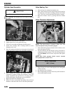
NOTE: Both feeler gauges should remain inserted
during adjustment of each valve
3. When clearance is correct, hold adjuster screw and tighten
locknut securely
4. Re-check the valve clearance.
5. Repeat adjustment procedure if necessary until clearance is
correct with locknut secured.
CAUTION
Wear eye protection during assembly.
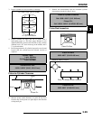
VALVE CLEARANCE
.006” (.15 mm)
Feeler gauge for both valves