


4.17
FUEL INJECTION
4
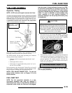
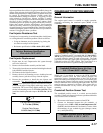
Injector problems due to dirt or clogging are unlikely due to the
design of the injectors, the high fuel pressure, the use of filters
and the detergent additives in the gasoline. Symptoms that could
be caused by dirty/clogged injectors include rough idle,
hesitation/stumble during acceleration, or triggering of fault
codes related to fuel delivery. Injector clogging is usually
caused by a buildup of deposits on the director plate, restricting
the flow of fuel, resulting in a poor spray pattern. Some
contributing factors to injector clogging include; dirty air filters,
higher than normal operating temperatures, short operating
intervals and dirty, incorrect, or poor quality fuel. Cleaning of
clogged injectors is not recommended; they should be replaced.
Additives and higher grades of fuel can be used as a preventative
measure if clogging has been a problem.
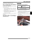
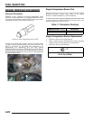
Fuel Injector Resistance Test
If an injector is not operating, it can indicate either a bad injector,
or a wiring/electrical connection problem. Check as follows:
• Using an ohmmeter, test for continuity by placing the
test leads on each pin of the injector.
• Resistance specification is 12.0
±0.4 (20°C, 68°F)
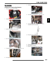
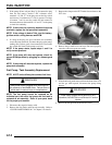
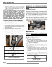
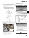
Fuel Injector Replacement
1. Engine must be cool. Depressurize fuel system through
test valve in fuel rail.
2. Remove the front fender assembly and fuel tank.
3. Thoroughly clean the area around and including the throttle
body/manifold and the injectors.
4. Disconnect the fuel injector harness.
5. Remove the fuel rail mounting screws, doubler plate and
carefully loosen / pull the rail away from the injector.
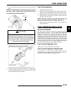
6. Reverse the procedures to install the new injector and
reassemble. Use new O-rings any time an injector is
removed (new replacement injectors include new O-rings).
Lubricate the upper O-ring lightly with soapy water to aid
installation. The lower O-ring should remain dry. Torque
the fuel rail mounting screws to 5~7 ft. lbs. (6-9 Nm). Then
install the doubler plate and torque to 8~9.5 ft. lbs. (11-13
Nm).
CRANKSHAFT POSITION SENSOR
(CPS)
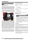
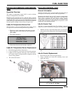
General Information
The engine speed sensor is essential to engine operation,
constantly monitoring the rotational speed (RPM) of the
crankshaft.
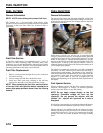
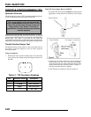
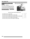
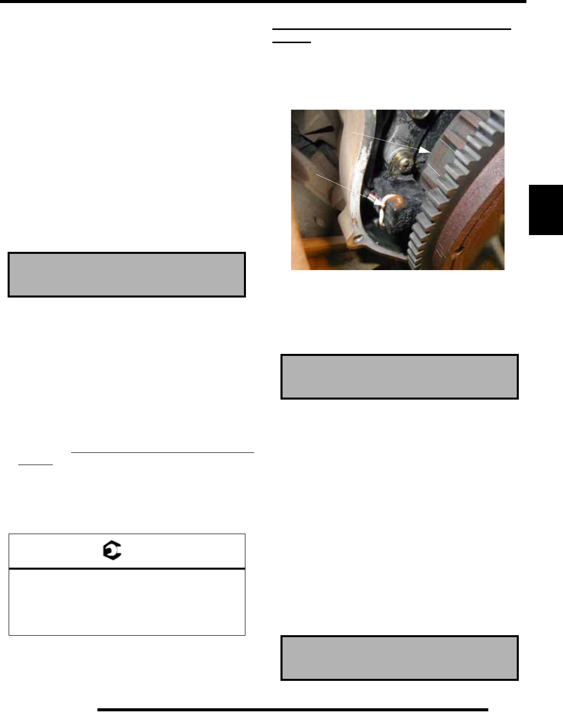
A ferromagnetic 36-1 ring gear is cast onto the flywheel. The
inductive crankshaft sensor is mounted 0.4 - 1.2 mm (0.015 -
.047 in.) away from this ring gear. During rotation, an AC pulse
is created within the sensor for each passing tooth. The tooth
gap creates an “interrupt” input signal, corresponding to specific
crankshaft position for PTO cylinder. This signal serves as a
reference for the control of ignition timing by the ECM.
Within one (1) revolution at start-up, the ECM calculates
crankshaft position from the time interval between the
consecutive pulses. Synchronization of the CPS, ECM and
MAP sensor takes place during the first two (2) revolutions each
time the engine is started. Once the engine is started, the ECM
monitors the MAP sensor for the engine intake stroke. The CPS
must be properly connected at all times. If the sensor fails or
becomes disconnected for any reason, the engine will quit
operating.
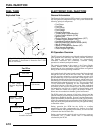
Crankshaft Position Sensor Test
The crankshaft position sensor is a sealed, non-serviceable
assembly. If fault code diagnosis indicates a problem within this
area, test and correct as follows:
1. Disconnect main harness connector from ECM.
2. Connect an ohmmeter between the pin terminals. A
resistance value of 185
20% at room temperature (20
C, 68 F) should be obtained. If resistance is correct, check
the mounting, air gap, toothed ring gear (damage, runout,
etc.), and flywheel key.
Injector Resistance Specification:
12.0 ±0.4 (20°C, 68°F)
= T
Fuel Rail Mounting Screws:
5~7 ft. lbs. (6-9 Nm)
Doubler Plate Screws
8~9.5 ft. lbs. (11-13 Nm)
Crankshaft Position Sensor Air Gap:
0.4 - 1.2 mm (0.015 - .047 in.)
Crankshaft Position Sensor Resistance:
185
± 20% @ (20° C , 68° F)
CPS
Interrupt