


5.19
BODY / STEERING / SUSPENSION
5
Ball Joint Replacement
NOTE: Refer to the illustration on the previous page
for this procedure.
1. Loosen front wheel nuts slightly.
2. Elevate and safely support machine under footrest/frame
area.
3. Remove wheel nuts and wheels.
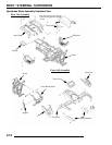
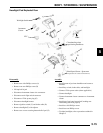
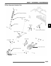
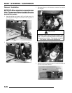
4. Remove cotter pin (A) from ball joint castle nut (B).
5. Remove castle nut (B) and separate A-arm (C) from ball
joint stud.
6. Remove screws (D) and ball joint retaining plate (E).
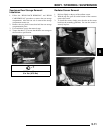
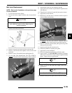
7. Use the Ball Joint Replacement Tool (PN 2870871),
remove
ball joint (F) from strut housing. Refer to photos.
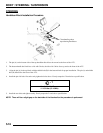
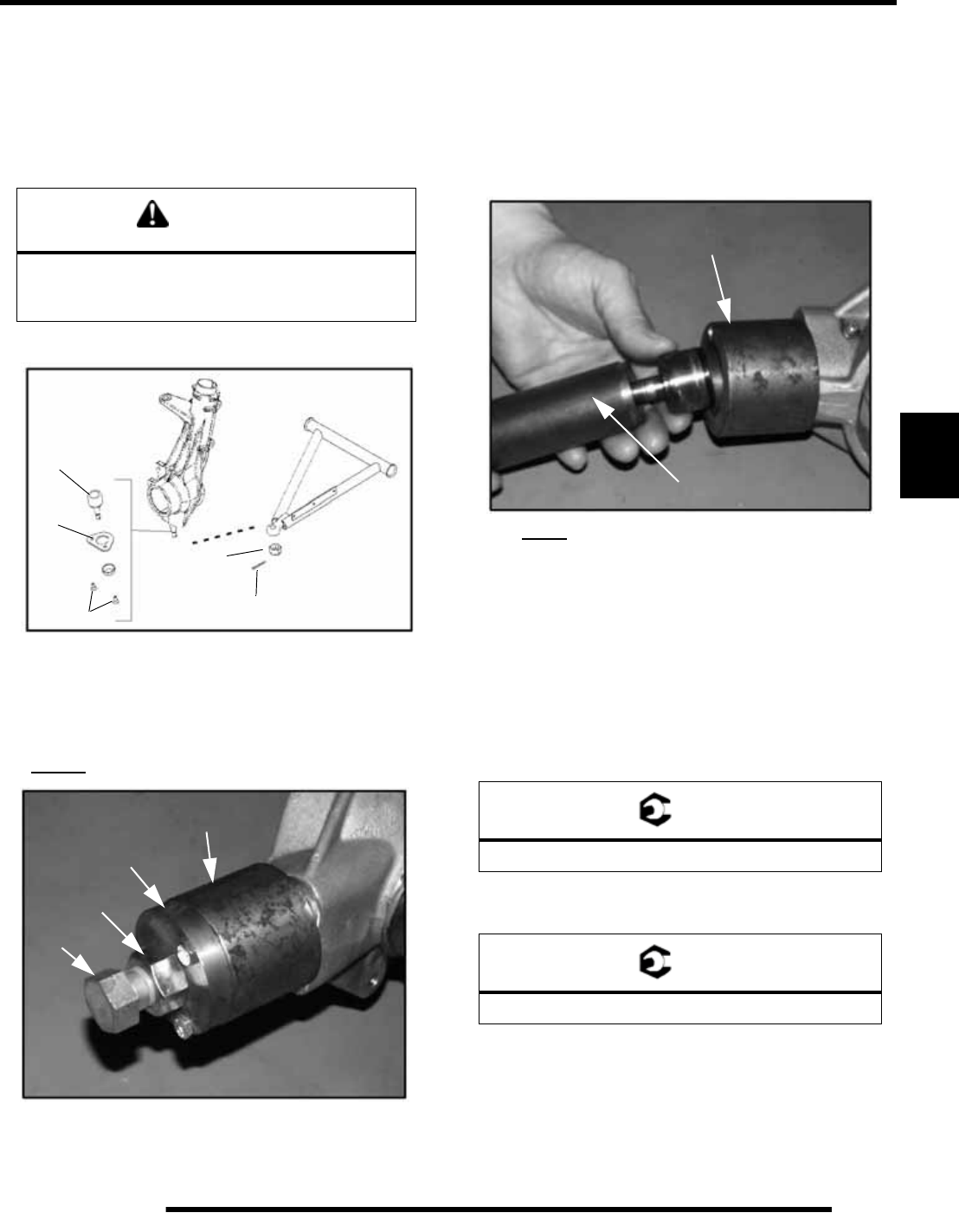
8. Install puller guide (G) with extension cap (H).
9. Apply grease to extension cap and threads of puller bolt to
ease removal.
10. Thread bolt (J) with nut (I) onto ball joint stud as shown.
11. Apply heat to ease removal.
12. Hold bolt (J) and turn nut (I) clockwise until ball joint is
removed from strut housing.
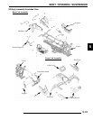
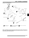
13. To install
a new ball joint, Remove extension cap and
attach puller guide using short bolts provided in the kit.
14. Remove extension cap and attach puller guide using short
bolts provided in the kit.
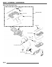
15. Insert new ball joint (K) into driver (L).
16. Slide ball joint/driver assembly into guide.
17. Apply heat to ease installation.
18. Drive new joint into strut housing until fully seated.
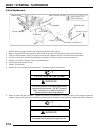
19. Apply Loctite
242 (PN 2871949) to threads of retaining
plate screws or install new screws with pre-applied locking
agent. Torque screws to specification.
20. Install A-arm on ball joint and torque castle nut to
specification.
21. Reinstall cotter pin with open ends toward rear of machine.
CAUTION
Serious injury may result if machine tips or falls. Be
sure machine is secure before beginning this
service procedure.
F
E
D
A
B
G
H
I
J
= T
Retaining Screw Torque: 8 ft. lbs. (11 Nm)
= T
Castle Nut Torque: 25 ft. lbs. (35 Nm)
K
L