


10.33
ELECTRICAL
10
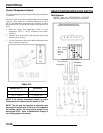
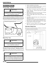
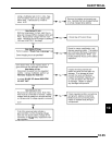
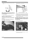
TEST 1: Resistance Value of Each Stator Leg
1. Measure the resistance value of each of the three stator legs: Y1 to Y2, Y1 to Y3, and Y2 to Y3. Each should measure 0.19
15 %.
NOTE: If there are any significant variations in ohm's readings between the three legs; it is an indication that
one of the three stator legs maybe weak or failed.
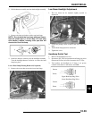
TEST 2: Resistance Value of Stator Leg to Ground
1. Measure the resistance value of each of the stator legs to ground: Y1 to Ground, Y2 to Ground, Y3 to Ground.
NOTE: Any measurement other than Infinity (open) will indicate a failed or shorted stator leg.
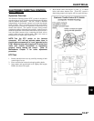
TEST 3: Measure AC Voltage Output of Each Stator Leg at Charging RPM
1. Set the selector dial to measure AC Voltage.
2. Start the engine and let it idle.
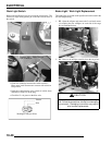
3. While holding the ATV at a specified RPM, separately measure the voltage across each “leg” of the stator by connecting the
meter leads to the wires leading from the alternator (Y1 to Y2, Y1 to Y3, Y2 to Y3).
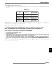
4. Refer to the table below for approximate Voltage AC readings according to RPM. Test each leg at the specified RPM in the
table. Example: The alternator voltage output reading should be no less than 30-40 Vac above 2000 RPM between each 'leg'.
NOTE: If one or more of the stator leg output AC voltage varies significantly from the specified value, the
stator may need to be replaced.
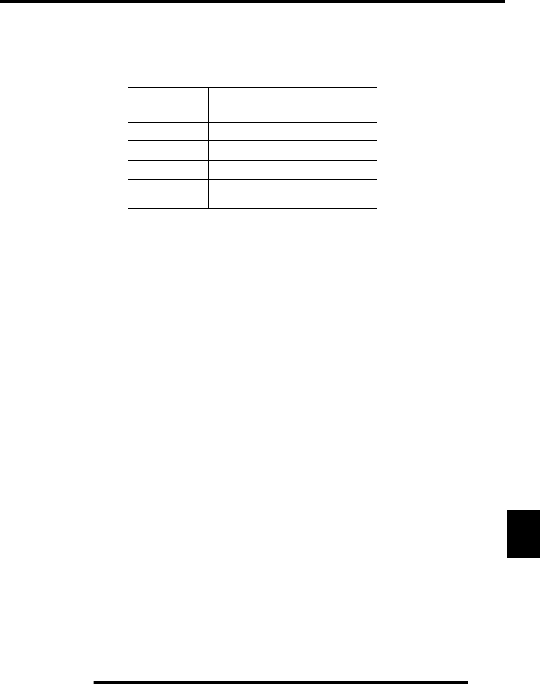
Table 10-2:
TEST
CONNECT METER
W
IRES TO:
R
EADING IN OHMS
Charge Coil Y1 to Y2
0.43
15%
Charge Coil Y1 to Y3
0.43
15%
Charge Coil Y2 to Y3
0.43
15%
Charge Coil
Y1, Y2, or Y3 to
Ground
Open (Infinity)