


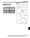

10.6
ELECTRICAL
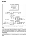
Battery Protected Output
The battery protected output (BAT_PROT) provides solid-
state-circuit-breaker (SSCB) outputs and enables most of the
functions on the PDM. The BAT_PROT output must be routed
only to the vehicle key/run switch for proper power up sequence.
BAT_PROT is enabled when the key/run switch connects the
BAT_PROT output to loads (must include RUN input). This
causes the micro-controller to power-up and energize
BAT_PROT. When RUN input goes high, the micro-controller
will remain ’ON’ until RUN input goes low by disconnection of
the BAT_PROT via the key switch or on/off switch. The
BAT_PROT output is protected from overloads and short
circuits. If this occurs, the output turns off. Once tripped, the
SSCBs can be reset by removing the overload or cycling the key/
run switches. The SSCBs will trip again if the issue causing the
overload is not removed.
Fan Relay Controller
The FAN relay is a smart high-side power switch. The FAN
controller requires the RUN input to be active and then is
enabled by the FAN_ON signal. The FAN output current is
monitored by the micro-controller. If the over-current limit is
exceeded for the amount of delay time programmed, the output
will shut off. If the maximum current limit is exceeded, the
current will shut off immediately. The micro-controller disables
the FAN output for a pre-programmed amount of time, then
resets the FAN relay. This will continue until the issue causing
the fault has been removed. When the FAN relay is off, the
micro-controller also monitors the output to see if the fan has
been disconnected.
Fan Status
The FAN_STAT output is control by the micro-controller.
FAN_STAT will go low only when the fan is off. For overloads
the FAN_STAT will go low after the pre-programmed delay
time. For an open fan condition, the micro-controller will wait
the programmed open-fan delay time and then indicate a fan
fault. The FAN_STAT output is current-limited.
Accessory Power:
The ACC_PWR switch uses a smart high-side power switch. It
is enabled when the RUN input is activated and disabled when
it’s removed. If the output current exceeds the short-circuit
limit, the output current will be reduced until the ACC_PWR
thermally shuts down. ACC_PWR will automatically turn back
on when it has cooled, based on thermal recovery. Repeated
cycles will cause the short-circuit limit to turn off repeatedly
until the overload has been removed.
Ignition Relay Output
The IGNITION relay uses a smart high-side power switch. The
IGNITION relay output is enabled when the RUN input is
activated and disabled when it’s removed. If the maximum
output current threshold is exceeded, the output current will be
reduced until the IGNITION circuit thermally shuts down.
IGNITION will automatically turn back on when it has cooled,
based on thermal recovery. Repeated cycles will cause the short-
circuit limit to turn off repeatedly until the overload has been
removed.
ECM Relay Output
The ECM_RELAY is a smart high-side power switch. The
ECM_RELAY relay output is enabled when the RUN input is
activated and KAP_EFI input is low. Once enabled,
ECM_RELAY stays activated until the KAP_EFI input goes
high. The ECM_RELAY output current is monitored by the
micro-controller. If the over-current threshold is exceeded for
the pre-programmed delay time, the output current will shut off.
Exceeding the power switch maximum current limit shuts down
the output immediately. Cycling the KAP_EFI via the key/run
switches will reset the output if RUN is active. Note: If RUN is
not active, the micro-controller powers down, therefore, the
maximum current limit will be the only overload protection
active until the KAP_EFI input disables the ECM_RELAY.
Fuel Pump Relay
The fuel pump circuit utilizes a and a smart high-side power
switch output. The FUEL_PUMP output is enabled when RUN
is activated and FUEL_EN is low. If the maximum output
current threshold is exceeded, the output current will be reduced
until the relay thermally shuts down. It will automatically turn
back on when it has cooled, based on thermal recovery.
Repeated cycles will cause the short-circuit limit to turn off
repeatedly until the overload has been removed.
Active Descent Control
An IPS is provided for current flow to the hub coil. The PDM
receives inputs from the TPS to determine throttle open/closed
and the Speed Sensor signal to determine vehicle speed.
ECM Memory
The ECM_MEM output is a current-limited, high-side power
switch for the ECM and cluster. This output is enabled whenever
battery power is connected to the PDM.
Reverse Polarity Protection
The reverse polarity protection circuit if in series with the
battery positive input of the PDM. It allows forward current to
flow with little voltage drop. When the battery terminals are
connected in reverse, the protection switch is forced off,
interrupting any current flow other than -2mA of bias current.
Light Output
The LIGHTS switch uses a smart-side power switch. The
LIGHTS output is enabled when the RUN input goes high and
disabled when it is low. If the output current exceeds the short-
circuit limit, the output current will be reduced until the device
thermally shuts down. It will automatically turn back on when
it has cooled, based on thermal hysteresis. Repeated cycles will
use the repetitive short-circuit limit to turn off until the overload
has been removed.
Starter Lockout
The starter lockout uses a low-side drive FET to connect the
ground side of the starter solenoid when the lockout is enabled.
To enable the lockout, the brake switch must be pulled high or
the transmission must be in Park or Neutral. The starter solenoid
positive side must be connected to BAT_PROT, as the lockout
relies on the current limit of BAT_PROT.
Differential Solenoid (X2 ONLY)
The differential solenoid driver provides a current-regulated
low-side drive for the solenoid coil. The low side driver sinks
current from the inductive load that is sourced internally via the
ACC_PWR output. The positive side of the differential solenoid
is current limited via ACC_PWR. To active the solenoid driver,
the TURF_MODE input must be high and the SPEED input
must read less than the solenoid speed limit. Once enabled, the
driver provides an initial “pull-in” current for a pre-determined
time and then lowers to a “hold” current until the TURF_MODE
input goes low or the TRANS input is in Park or Neutral and the
SPEED is less than the solenoid speed limit.