


3.34
ENGINE
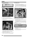
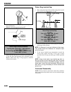
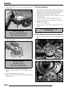
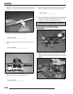
9. Measure pump end clearance using a feeler gauge and
straight edge.
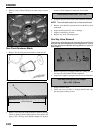
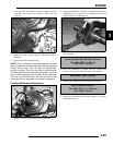
10. Measure clearance between outer feed rotor and pump body
with a feeler gauge.
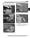
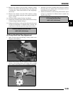
11. Measure rotor tip clearance with a feeler gauge.
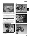
12. Remove inner and outer feed rotor and pump chamber
body.
13. Repeat measurements for scavenge rotor.
14. Remove inner and outer scavenge rotor and inspect pump
shaft for wear.
Oil Pump Assembly
1. Clean and dry all parts thoroughly. Apply clean engine oil
to all parts. Do not use gasket sealer on the pump body
mating surfaces or oil passages will become plugged.
2. Install pump shaft and scavenge rotor drive pin.
3. Install outer scavenge rotor, inner scavenge rotor, and
scavenge casing.
4. Install outer feed rotor and inner feed rotor drive pin.
5. Install inner feed rotor and feed chamber cover with screw.
6. Tighten screw securely.
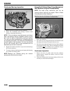
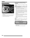
7. Install screen on pump body.
8. Install oil pump on crankcase and torque bolts to 6 ft. lbs.
(8 Nm).
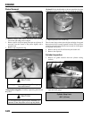
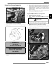
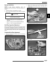
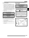
Counter Balancer Shaft Removal/Inspection
1. Remove the shim washer (A) from the counter balancer
shaft.
2. Note the alignment dots on the balancer and crankshaft
gears, the marks must be aligned during reassembly.
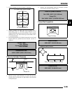
Pump End Clearance:
Std: .001 -.003 (.0254-.0762 mm)
Wear Limit: .004 (.1016 mm)
Rotor Tip Clearance:
Std: .005 (.127 mm)
Wear Limit: .008 (.2032 mm)
Oil Pump Attaching Bolt Torque:
6 ft. lbs. (8 Nm)
A