


6.32
CLUTCH SYSTEM
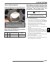
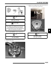
Drive Clutch Bushing Installation
1. Place main adapter on puller.
2. Apply Loctite 609 evenly to bushing bore inside
moveable sheave.
3. Set bushing in place on sheave.
4. Insert installation puller tool into center of bushing.
5. With towers pointing upward, slide sheave, bushing and
tool onto puller rod.
6. Install nut on puller rod and hand tighten. Turn barrel to
apply additional tension if needed.
7. Turn sheave counterclockwise, making sure bushing is
drawn straight into bore. Continue until bushing is seated.
8. Remove nut from puller rod and set aside.
9. Remove sheave from puller.
10. Remove installation tool.
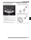
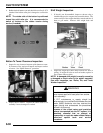
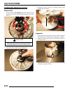
Cover Bushing Removal
1. Install main adapter on puller.
2. Install adapter reducer.
3. From outside of clutch cover, insert removal tool into cover
bushing.
4. With inside of cover toward vise, slide cover onto puller.
5. Install nut onto puller rod and hand tighten. Turn puller
barrel to increase tension as needed.
6. Turn clutch cover counterclockwise on puller rod until
bushing is removed and cover comes free.
7. Remove nut from puller rod and set aside.
8. Remove bushing and bushing removal tool from puller.
Discard bushing.
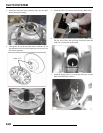
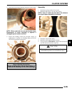
Cover Bushing Installation
1. Apply Loctite 609 evenly to bushing bore in cover.
2. Working from inside of cover, insert new bushing and
bushing installation tool into center of clutch cover.
3. With main adapter on puller, insert cover onto puller rod,
placing outside of cover toward vise.
4. Install nut on rod and hand tighten. Turn puller barrel to
apply more tension if needed.
5. Turn clutch cover counterclockwise on puller rod until
bushing is seated.
6. Remove nut from puller rod. Take installation tool and
clutch cover off rod.
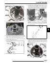
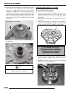
Drive Clutch Reassembly
NOTE: It is important that the same number and
thickness of washers are reinstalled beneath the
spider during assembly. The Teflon bushings are
self-lubricating. Do not apply oil or grease to the
bushings.
Reassemble drive clutch in the following sequence. Be sure the
“X”, or the marks that were made earlier, are aligned during
each phase of assembly.
A) “X”, or the marks that were made earlier on cover
B) “X” on spider, making sure spacer washers are installed
underneath spider and positioned properly in recess
C) “X”, or the marks that were made earlier under weight
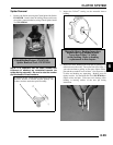
1. Install moveable sheave onto fixed sheave.
2. Install spider spacers. Use same quantity and thickness as
were removed.
3. Compress spider buttons for each tower and install spider
towers on the moveable sheave. Verify that the alignment
marks on spider align with the marks that were made on the
moveable sheave.
4. Torque spider to specification using the holding fixture and
spider tool. Torque with smooth motion to avoid damage
to the stationary sheave.