


4.21
FUEL INJECTION
4
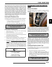
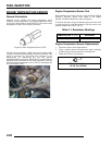
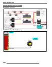
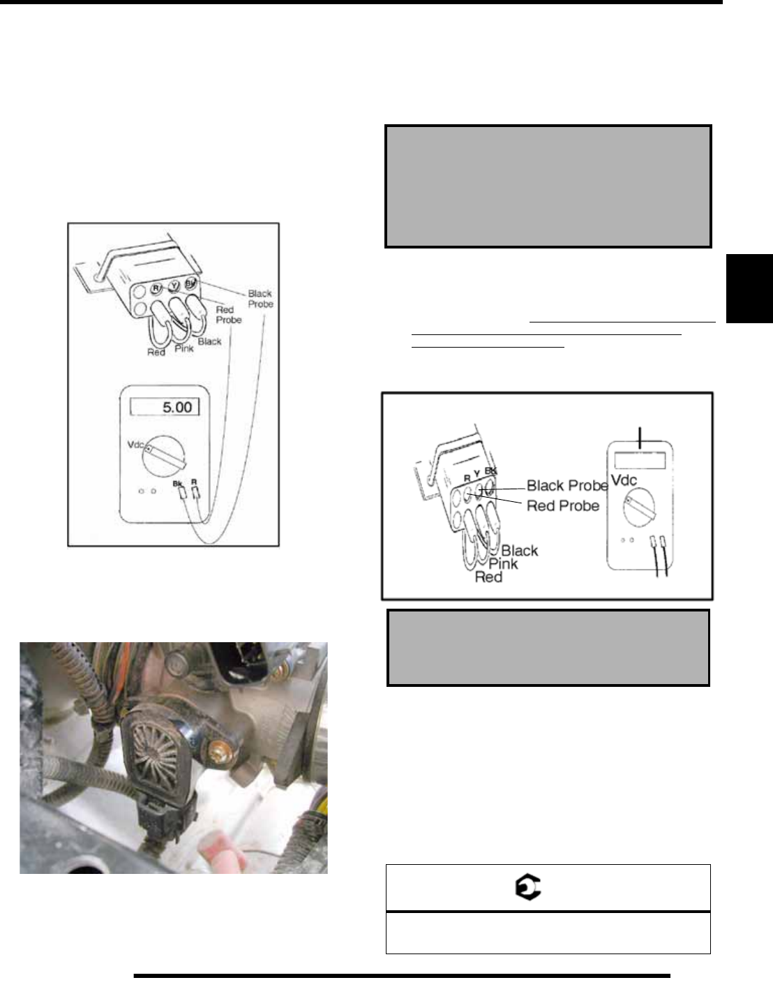
Tps Tester - Correct Reference Voltage
A 5 volt reference voltage signal from the test harness is
required for the TPS test to be accurate. Refer to the instructions
provided with the TPS Test Adapter Harness (2201519) or
follow these steps to check reference voltage.
• Harness Test: Insert black voltmeter probe into the
“Bk” test port.
• Connect the red meter probe into the “R” port and
verify the voltage is 4.99-5.01 vdc. If this reading is
low, verify the 9 volt battery is good or try a new 9 volt
battery.
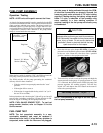
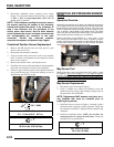
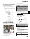
Throttle Position Sensor Replacement
NOTE: The correct position of the TPS is established and set at
the factory. If the TPS is repositioned, replaced or loosened it
must be recalibrated.
1. Remove the LH side panel assembly.
2. Disconnect sensor from the engine harness.
3. Loosen and rotate the throttle body (B) to gain access to the
retaining screws (if required).
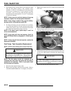
4. Remove the retaining screws and replace the sensor, but do
not tighten the screws at this point.
5. Refer to “TPS Initialization” for setting the TPS voltage.
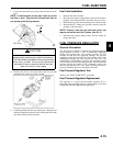
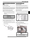
Throttle Position Sensor (Tps) Initialization
Establishing a TPS setting : This step is crucial as it sets the
TPS position using the fixed physical stop.
• Open and close throttle plate a couple of times to ensure
full throttle closing. Do not snap closed, as this could
cause unnecessary throttle plate to throttle body
interference and/or damage.
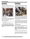
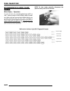
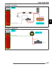
• Set up the TPS Test Adapter Harness 2201519. Verify
that the 9 volt battery is new. Figure 2.
• (NOTE: Applies to 500 EFI ONLY) Attach the RED
meter lead to the “R” port and BLACK meter lead to
the “Y” port of the TPS Tester Harness
2201519, verify the voltage output of the TPS reads
1.10 - 1.14 vdc.
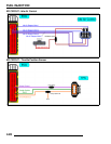
• If it does not read 1.10 - 1.14 vdc, loosen the screws
holding the TPS to the throttle body. Rotate TPS until
voltmeter reads 1.10 - 1.14 vdc.
• Retighten TPS mounting screws to specification and
verify the voltage did not change.
The correct position of the throttle body idle
stop is established and set at the factory. Do not
loosen the throttle body idle stop or alter the
stop position in any fashion. If the stop is
repositioned, the entire throttle body assembly
must be replaced.
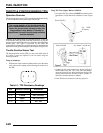
500 EFI engines - Apply RED meter lead to the “R”
port and BLACK meter lead to the “Y” port of TPS
Tester Harness to obtain correct reading.
= T
TPS Retaining Screws:
17.7 in. lbs. (2 ± 0.5 Nm)
TPS Tester Adapter
Harness- 2201519
Fig. 2
1.12v
Should Read: 1.10 - 1.14 vdc