


6.21
CLUTCH SYSTEM
6
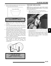
C) “X”, or the marks that were made earlier under weight
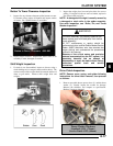
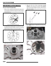
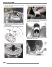
2. Install moveable sheave onto fixed sheave.
3. Install spider spacers. Use same quantity and thickness as
were removed.
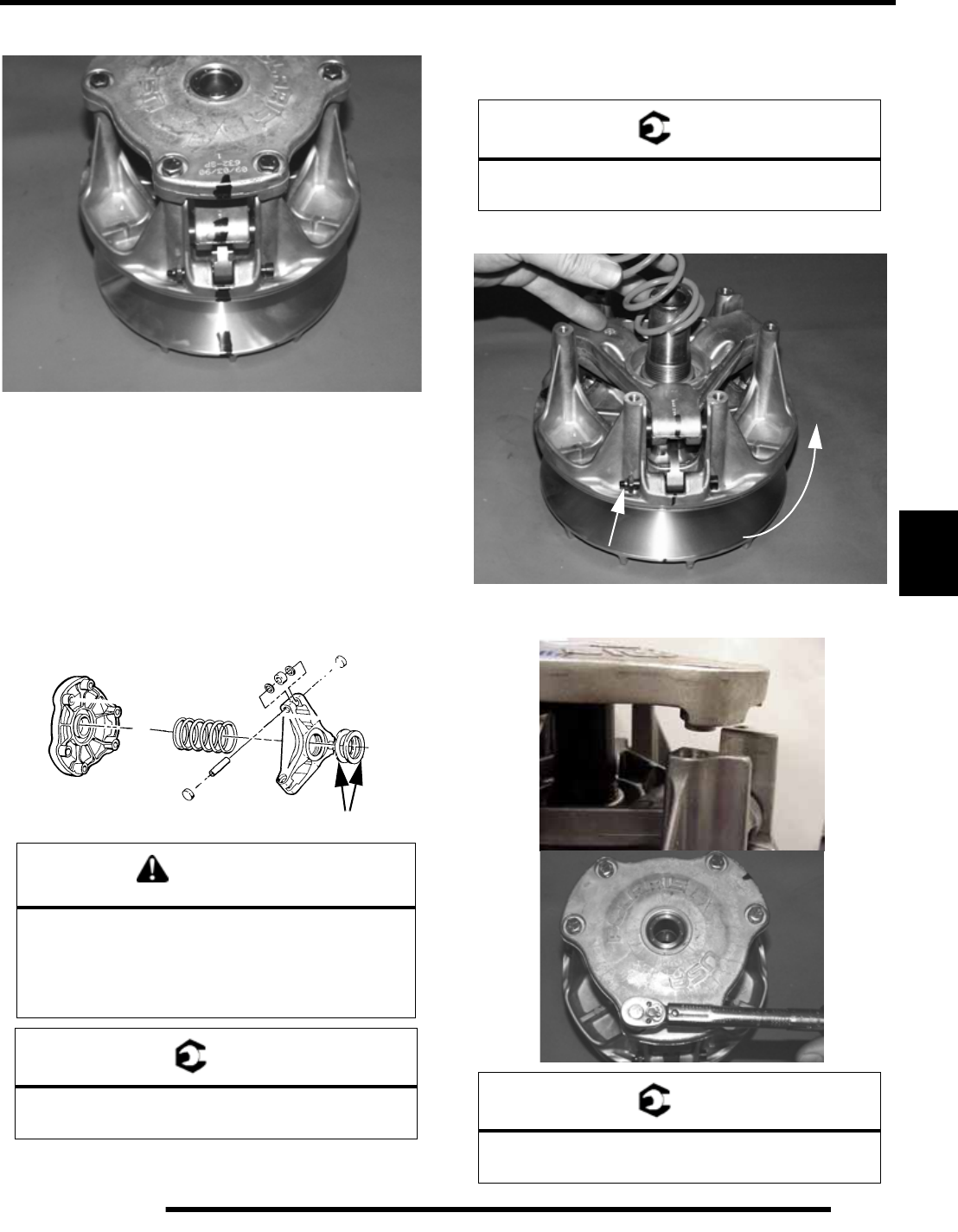
4. Compress spider buttons for each tower and install spider,
making sure that “X”, or the marks that were made earlier,
on spider aligns with “X”, or the marks that were made
earlier on the moveable sheave.
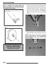
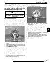
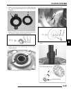
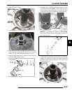
5. Torque spider to specification using the holding fixture and
spider tool. Torque with smooth motion to avoid damage
to the stationary sheave.
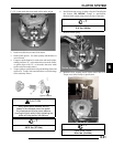
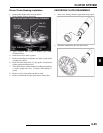
6. Install limiter nut on top of spider using the Clutch Spider
Nut Socket (PN 2870338). Torque to specification.
Reinstall shift weights using new lock nuts on the bolts.
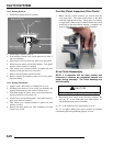
7. Reinstall clutch spring.
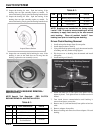
8. Reinstall cover, aligning bosses on the tower and cover.
Torque cover bolts evenly to specification.
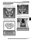
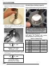
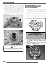
CAUTION
Verify spider spacer washers are fully
seated in the recessed area of the spider.
Any misalignment will alter clutch balance.
Inverting the clutch while initially tightening the
spider will help position the washers.
= T
Spider Torque:
200 ft. lbs. (271 Nm)
Spacer Washers
= T
Spider Nut Torque:
15 ft. lbs. (20 Nm)
= T
Cover Screw Torque:
90 in. lbs. (10.4 Nm)
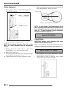
Engine
Rotation
Nut on trailing side