


9.25
BRAKES
9
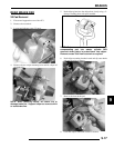
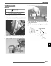
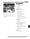
NOTE: The slide pins should be torqued when
installed on caliper mount.
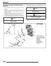
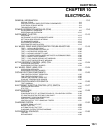
4. Install caliper and torque mounting bolts to specification.
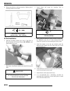
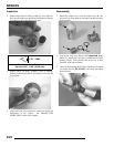
5. Install brake line and tighten securely with a line wrench.
Torque the brake lines to the proper torque specification.
6. Follow bleeding procedure outlined in the “BLEEDING
PROCEDURE” in this chapter.
7. Field test unit for proper braking action before putting into
service. Inspect for fluid leaks and firm brakes. Make sure
the brake is not dragging when lever is released. If the brake
drags, re-check assembly and installation.
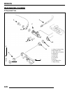
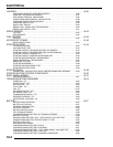
REAR BRAKE DISC
Inspection
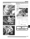
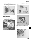
1. Visually inspect disc for scoring, scratches, or gouges.
Replace the disc if any deep scratches are evident.
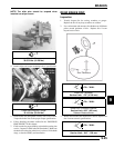
2. Use a micrometer and measure disc thickness at 8 different
points around perimeter of disc. Replace disc if worn
beyond service limit.
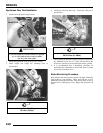
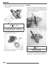
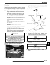
3. Mount dial indicator and measure disc runout. Replace the
disc if runout exceeds specifications.
= T
Slide Pin Torque:
30-35 ft.lbs. (41-48 Nm
)
= T
Caliper Mounting Bolt Torque:
16-18 ft.lbs. (22-24 Nm
)
18 ft.lbs.
(24 Nm)
30-35 ft.lbs.
(41-48 Nm)
= In. / mm.
Brake Disc Thickness:
Service Limit: .170” (4.318 mm)
= In. / mm.
Brake Disc Thickness Variance:
Service Limit: .002” (.051 mm)
Between Measurements
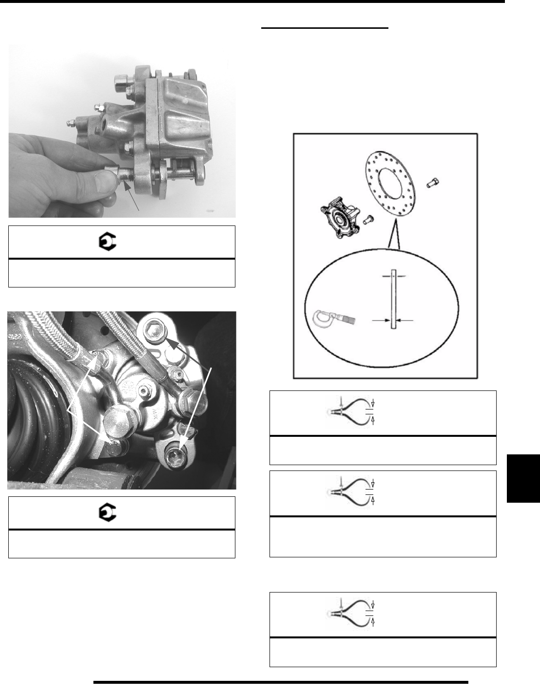
= In. / mm.
Brake Disc Runout
Service Limit: .010” / .254 mm
Disc Thickness