


4.18
FUEL INJECTION
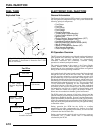
3. Disconnect crankshaft sensor connector from wiring
harness. Test resistance between the terminals. A reading
of 185
20% at room temperature (20C, 68 F)
should again be obtained.
NOTE: If the resistance reading is incorrect, remove
the screws securing the sensor to the mounting
bracket and replace the sensor. If the resistance in
step 2 was incorrect, but the resistance of the
sensor alone was correct, test the main harness
circuit between the sensor connector terminals and
the corresponding pin terminals in the main
connector. Correct any observed problem,
reconnect the sensor, and perform step 2 again.
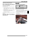
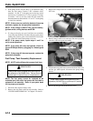
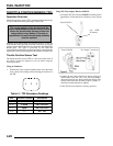
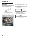
Crankshaft Position Sensor Replacement
1. Remove the RH footwell and rear body panel to gain
access to the recoil cover.
2. Disconnect sensor harness connector.
3. Using an 8 mm socket, remove the recoil cover retaining
bolts. A mallet or soft hammer may be required to loosen
the cover for removal.
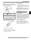
4. Remove the retainer screws securing the sensor.
5. Install the new sensor, routing the harness wire through the
top of the case housing as was previously installed.
6. Set the air gap of the new sensor to the specified distance
away from the ring gear. Torque the retaining screws to
specification and reverify air gap.
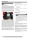
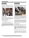
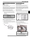
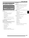
MANIFOLD AIR PRESSURE SENSOR
(MAP)
Operation Overview
Mounted on the throttle body intake, the manifold air pressure
sensor (MAP) measures air passing and provides the ECM with
the manifold pressure during engine operation. This allows the
ECM to adjust the fueling according to actual engine load as
well as identify which stroke is the intake stroke. The MAP
sensor also provides the ECM with the ability to compensate for
high altitude operation without any recalibration.
During initial start-up, the ECM is in a “waste spark - waste
fuel” mode until the MAP sensor sends a negative pressure
reading, indicating that the engine is on the intake stroke. Once
this has been ‘learned’, the ECM will then monitor the MAP
sensor and cease the initial start-up program.
Map Sensor Test
MAP sensors are a non-serviceable item. If it is faulty, it must
be replaced. This sensor requires a 5 Vdc input to operate,
therefore the MAP sensor should only be tested using Polaris
Diagnostic Software (dealer only). Refer to the EFI Diagnostic
Software Manual for more information.
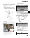
Map Sensor Replacement
1. Disconnect sensor from engine harness.
2. Using a suitable tool, remove the retaining screw and
replace the sensor, using a light coating of soapy water on
the grommet to aid installation.
NOTE: Replacement MAP sensors may have an o-
ring installed that must be removed prior to
installing the grommet.
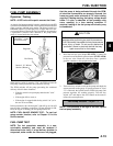
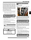
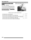
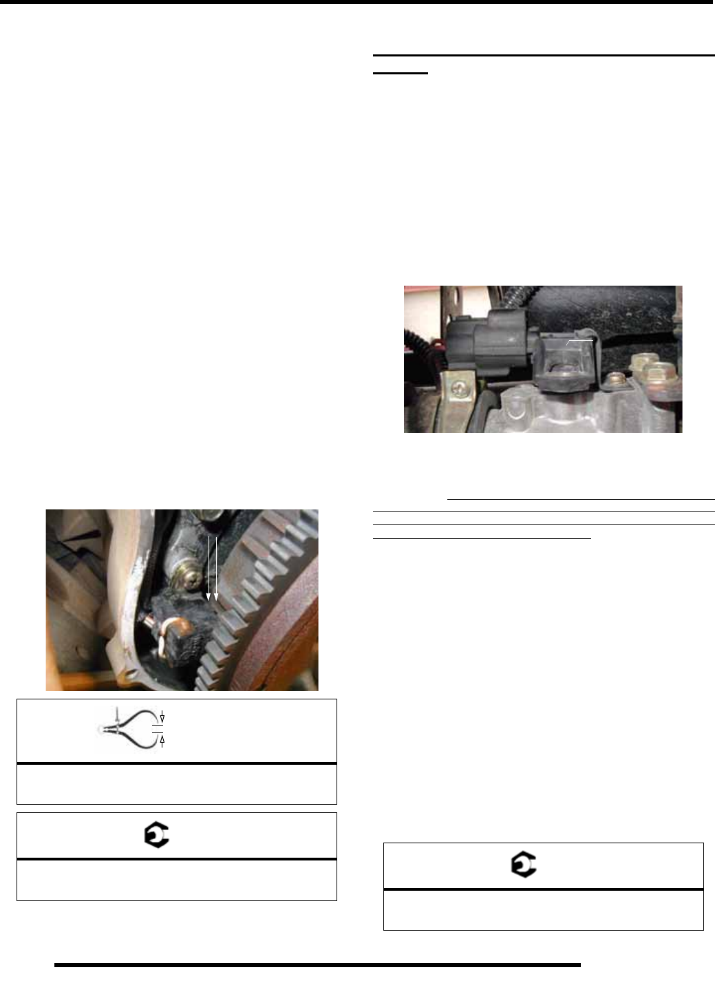
3. Install the sensor as shown in Figure 1, inserting it with a
twisting motion to properly seat the grommet. Verify that
the connector centerline is aligned with the throttle body
centerline.
4. Install the retaining bracket. NOTE: Do not allow the
retaining bracket to contact the MAP body. Torque the
retaining screw to specification.
= In. / mm.
CPS Air Gap:
0.4 - 1.2 mm (0.015 - .047 in.)
= T
CPS Retaining Screws:
26-34 in. lbs. (2.9-3.92 Nm)
0.4 - 1.2 mm (0.015 -
.047 in.)
= T
MAP Retaining Screw:
29 in. lbs. (3.3 Nm)
Do not allow bracket to contact MAP