


10.11
ELECTRICAL
10
the micro-controller will remain 'ON' until RUN input goes low
by disconnection of the BAT_PROT via the key switch or on/off
switch. It will remain 'ON' for 5 seconds before turning off The
BAT_PROT output is protected from overloads and short
circuits. If this occurs, the output turns off. Once tripped, the
SSCBs can be reset by removing the overload or cycling the key/
run switches. The SSCBs will trip again if the issue causing the
overload is not removed.
Engine Temperature Controller
The engine temperature controller has several features and two
outputs: HOT INDICATOR and FAN. The engine hot output is
low and sinks the indicator signal to ground. The fan output is
active high and sources battery power to turn on the fan. The
controller's primary function is to control the fan motor. The fan
motor is turned on and off at pre-set resistances as determined
by the engine temperature thermistor. The FAN output is
protected against short circuit and overload. If the fan current
exceeds the overload limit longer than the time allowed for
inrush, the fan will shut off and the HOT INDICATOR will turn
on. After a delay, the FAN output will then reset itself and turn
on again. If the overload persists, the controller will cycle the
FAN output on and off at set interval until the overload is
removed. If the maximum temperature of the switching device
is exceeded the fan output will turn off. The fan will cycle on and
off as previously described until the device temperature drops.
The FAN output driver also monitors to see if the fan is
connected during 'ON' state only. If the FAN output is open
circuit upon power up, the engine temperature controller will
activate the hot indicator. If the engine temperature exceeds the
engine hot thermistor limit, or detects a fan overload condition,
the hot indicator will activate. The controller also contains
provisions for detecting an open or shorted thermistor. A
thermistor fault will cause the engine hot indicator and FAN
output to activate.
Accessory Power:
The ACC_PWR switch uses a smart high-side power switch. It
is enabled when the RUN input is activated and disabled when
it's removed. If the output current exceeds the short-circuit limit,
the output current will be reduced until the ACC_PWR
thermally shuts down. ACC_PWR will automatically turn back
on when it has cooled, based on thermal recovery. Once tripped,
this output will remain off until the key switch is cycled on and
off again.
Lights Output
The LIGHTS output uses a smart high-side power switch. The
LIGHTS relay output is enabled when the RUN input is
activated and disabled when it's removed. If the maximum
output current threshold is exceeded, the output current will be
reduced until the LIGHTS circuit thermally shuts down. Once
tripped, this output will remain off until the key switch is cycled
on and off again.
HOT Indicator Output
The HOT Indicator output uses a low-side power switch 'smart
FET' that indicates when the thermistor input exceeds the values
programmed in the PDM. It also indicates a stalled or open fan
condition. The output is protected against shorts to battery, over-
load, over-voltage and over-temperature conditions.
Starter Lockout
Starter Lockout monitors the brake input and transmission
signal to determine if the STARTER output FET will enable a
ground path for the starter solenoid. The output is enabled if
either the BRAKE input is high or the TRANS signal voltage
indicates PARK or NEUTRAL. TRANS voltage is based on a
5Vdc power supply with a 220-ohm with 24-ohm for park and
160-ohm for neutral. RUN input must be enabled for the starter
lockout to function. This output is overload and short circuit
protected by the BAT-PROT output on the high side.
Reverse Polarity Protection
The reverse polarity protection circuit is in series with the
battery positive input of the PDM. It allows forward current to
flow with little voltage drop. When the battery terminals are
connected in reverse, the protection switch is forced off,
interrupting any current flow other than -2mA of bias current.
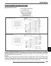
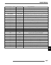
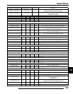
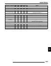
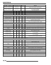
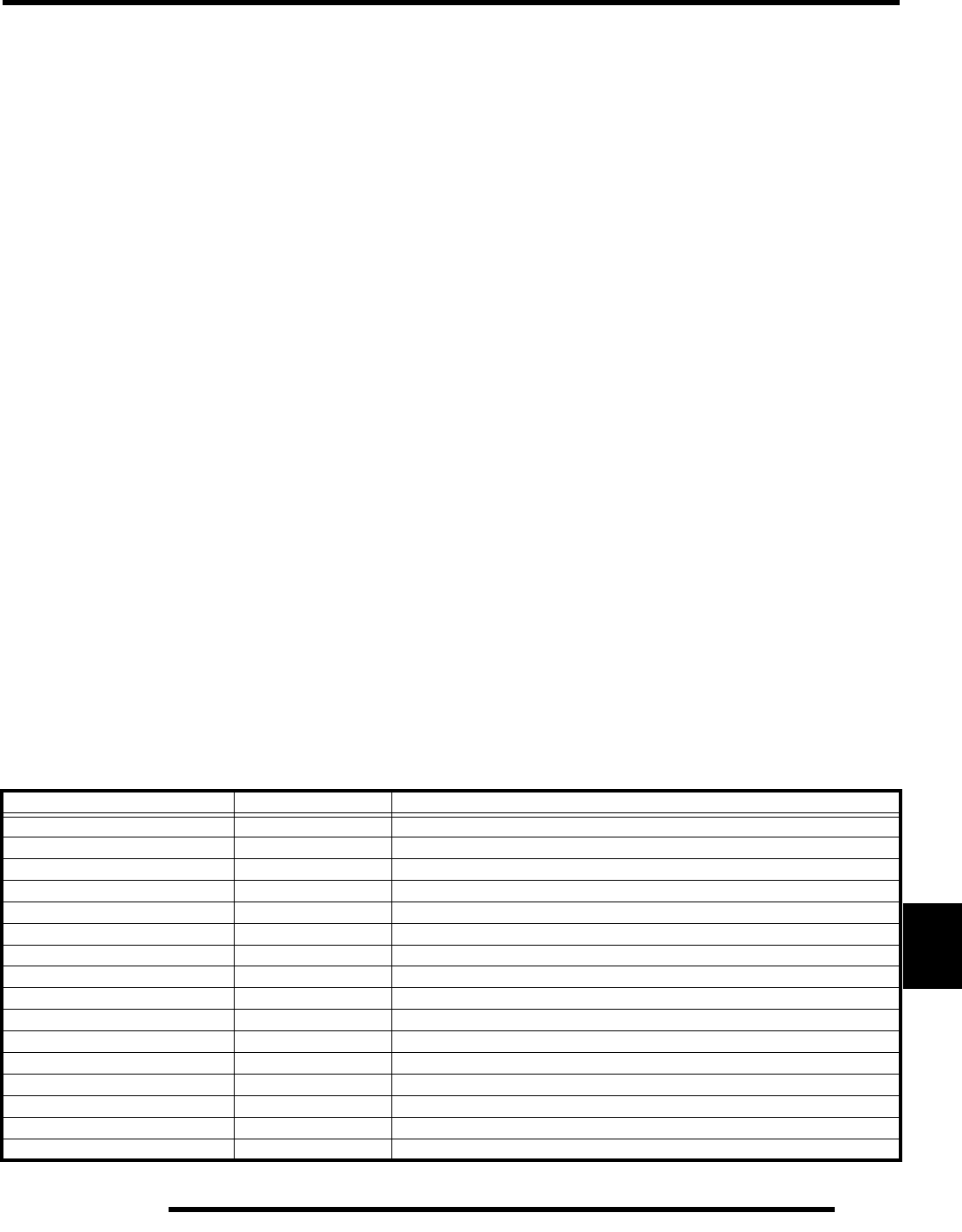
CONNECTOR 1 - PIN # SIGNAL NAME DESCRIPTION - IPS = Intelligent Power Switch
J1-A
STARTER
Starter output provides ground path when active.
J1-B
BRAKE
Brake input for starter lockout. Active high.
J1-C
RUN
PDM enable input. Connected to BAT_PROT via ignition and run
J1-D
HOT_INDICATOR
Engine hot signal. Provides a ground path for the hot indicator lamp
J1-E
THERM_RTN
Thermistor ground
J1-F
THERM
Thermistor input
J1-G
TRANS
Transmission signal voltage input for starter lockout
J1-H
LIGHTS
Powers vehicle lighting
J1-J
COIL 3
Alternator coil input
J1-K
COIL 2
Alternator coil input
J1-L
COIL 1
Alternator coil input w/resistance to ground
J1-M
BAT+
Battery Positive
J1-N
ACC_PWR
Battery Ground
J1-P
GND
Cathode side of AWD circuit
J1-R
BAT_PROT
SSCB output provides battery power to loads
J1-S
FAN
Relay control input to enable operation of the fan