


6.28
CLUTCH SYSTEM
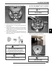
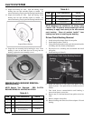
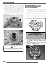
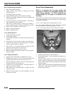
15. Install the cam assembly (helix) over the shaft. Line up the
“X” on the cam, “X” on spider, and “X” on the stationary
sheave or use the marks previously made before
disassembly. NOTE: If the cam assembly (helix) is
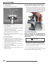
difficult to install, be sure the sheaves are aligned. To align
the sheaves place the clutch assembly on a flat surface with
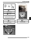
the cam assembly (helix) side down. Press down on the
moveable sheave belt face with both hands and the helix
will release.
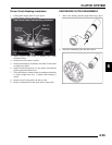
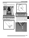
16. Use a T25 torx to install the four torx screws and torque to
specification.
STANDARD DRIVE CLUTCH
Drive Clutch Disassembly
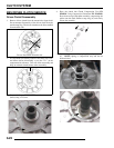
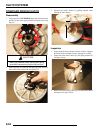
1. Using a permanent marker, mark the cover, spider, and
moveable and stationary sheaves for reference, as the
previous “X's” may not have been in alignment before
disassembly.
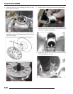
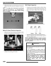
2. Remove cover bolts evenly in a cross pattern and remove
cover plate.
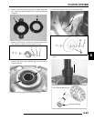
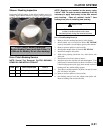
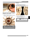
3. Inspect cover bushing (A). The outer cover bushing is
manufactured with a Teflon
coating. Wear is determined
by the amount of Teflon
remaining on the bushing.
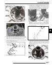
4. Inspect area on shaft where bushing rides for wear, galling,
nicks, or scratches. Replace clutch assembly if worn or
damaged.
5. Remove and inspect spring. See “Drive Clutch Spring
Specifications” for spring inspection.
= T
T25 Torx:
42-52 in. lbs. (4.75 - 5.88 Nm)
Press Down to Loosen Helix
Cover Bushing Inspection:
Replace the cover bushing if more
brass than Teflon is visible on
the bushing. Refer to bushing
replacement in this chapter.
A
Inspect Shaft