


8.3
GENERAL INFORMATION
8
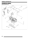
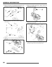
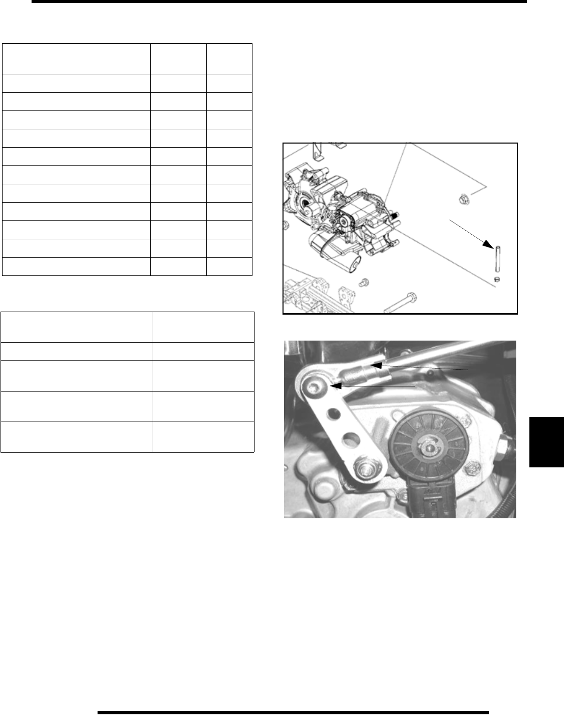
Torque Specifications
Special Tools
Lubrication
Refer to Chapter 2 for transmission lubricant type and capacity.
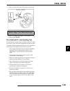
Gear Selector Removal
1. Disconnect linkage rod from gear selector handle.
2. Remove two bolts attaching gear selector mount to machine
frame.
3. Lift gear selector out of mounting bracket and away from
frame.
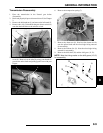
Transmission Removal
1. Place vehicle in “park”. Raise and securely support rear of
ATV at the frame. Remove both rear wheels.
2. Drain transmission lubricant (if required).
3. Remove seat, both side panels, both rear cab quarter panels
and both footwells. See Chapter 5.
4. Disconnect the differential, speed sensor and gear selection
switch connectors from the transmission.
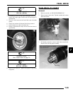
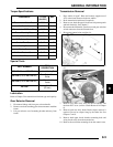
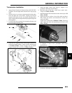
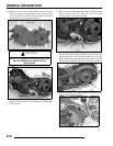
5. Disconnect transmission vent line (A).
6. Disconnect shift rod end (B) from transmission bellcrank
(C).
7. Remove PVT outer cover, drive and driven clutches, and
the inner PVT cover. (refer to Clutch Removal in Chapter
6).
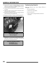
8. Remove both rear drive shafts. Brake caliper removal is
required. Do not let calipers hang by the brake line. See
Chapters 7 and 9.
9. Remove both upper shock absorber mounting bolts and
swing shocks away from the transmission.
10. Remove the torsion bar mountings from the control arms.
COMPONENT FT. LBS.
(IN.LBS.)
NM
Transmission Case Bolts 25-30 36-43
Bell Crank Nut 12-18 17-26
Transmission Fill/Drain Plug 20-25 29-36
Trans. Mounting Bolts 40 57
Gear Sector Cover 8-12 11-17
Oil Deflector Screws (20-30) 2-3.6
Snorkel Torx Screw 8-12 11-17
Bearing Cover 8-12 11-17
Carrier Cover 23-27 33-39
Shift Fort Retainer Screws 8-12 11-17
Park Plate 8-12 11-17
PART NUMBER
TOOL
DESCRIPTION
2871695 (Part of 2871702 Kit) Backlash Setting Tool
2871698 (Part of 2871702 Kit)
Rear Output Seal
Driver
2871699 (Part of 2871702 Kit)
Rear Driveshaft Seal
Guide
2871282
Bearing Seal Driver
(50 mm)
A
C
B