


4.10
FUEL INJECTION
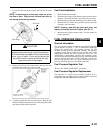
FUEL TANK
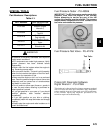
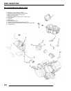
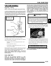
Exploded View
ELECTRONIC FUEL INJECTION
General Information
The Electronic Fuel Injection (EFI) system is a complete engine
fuel and ignition management design. This system contains the
following principal components:
•Fuel Pump
• Fuel Rail
• Fuel Line(s)
•Fuel Filter(s)
• Fuel Injector
• Pressure Regulator
• Throttle Body / lntake Manifold
• Engine Control Module (ECM)
• Ignition Coils
• Engine Coolant Temperature Sensor (ECT)
• Throttle Position Sensor (TPS)
• Crankshaft Position Sensor (CPS)
• Manifold Absolute Pressure Sensor (MAP)
• Idle Air Control (IAC)
• Intake Air Temperature Sensor (IAT)
• Wire Harness Assembly
• Check Engine Light (MIL)
Efi Operation Overview
The EFI system is designed to provide peak engine performance
with optimum fuel efficiency and lowest possible emissions.
The ignition and injection functions are electronically
controlled, monitored and continually corrected during
operation to maintain peak performance.
The central component of the system is the Visteon Engine
Control Module (ECM) which manages system operation,
determining the best combination of fuel mixture and ignition
timing for the current operating conditions.
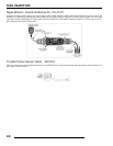
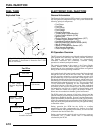
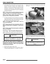
An in-tank electric fuel pump is used to move fuel from the tank
through the fuel line and in-line fuel filter. The in-tank fuel
pressure regulator maintains a system operating pressure of 39
psi and returns any excess fuel to the tank. At the engine, fuel is
fed through the fuel rail and into the injector, which injects into
the intake port. The ECM controls the amount of fuel by varying
the length of time that the injectors are "on." This can range from
1.5-8.0 milliseconds depending on fuel requirements. The
controlled injection of the fuel occurs every other crankshaft
revolution, or once for each 4-stroke cycle. The total amount of
fuel needed for one firing of a cylinder is injected during each
cycle. When the intake valve opens, the fuel/air mixture is
drawn into the combustion chamber, ignited and burned.
The ECM controls the amount of fuel being injected and the
ignition timing by monitoring the primary sensor signals for air
temperature, manifold absolute pressure, engine temperature,
engine speed (RPM), and throttle position (load). These primary
signals are compared to the programming in the ECM computer
chip, and the ECM adjusts the fuel delivery and ignition timing
to match the values.
During operation the ECM has the ability to re-adjust
temporarily, providing compensation for changes in overall
engine condition and operating environment, so it will be able
to maintain the ideal air/fuel ratio.
During certain operating periods such as cold starts, warm up,
acceleration, etc., a richer air/fuel ratio is automatically
calculated by the ECM.
1. Cap 2. Tank Vent In/Out 3. Tank Mount 4. Fuel Pump/
Tank Assembly 5. Seat Foam 6. Protective Foil 7. Fuel
Lines 8. Fuel Filter
1
2
3
4
6
5
8
7
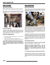
Fuel Tank
* Fuel Filter
(30 micron)
* Fuel Pump /
Pressure Regulator
Unit
External Fuel
Filter - 10 micron
Fuel Supply Rail
Injectors
Fuel Flow
* component
located in fuel tank