


10.47
ELECTRICAL
10
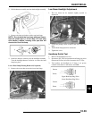
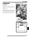
4. Inspect surface of commutator for wear or discoloration.
See Steps 3-6 of ‘Armature Testing’.
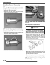
Brush Inspection
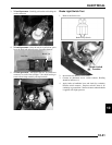
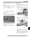
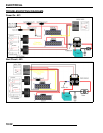
1. Measure length of each carbon brush. Replace brush
assembly when worn to 5/16” (8 mm) or less. The brushes
must slide freely in their holders.
Brush Replacement
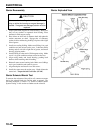
1. Install a new carbon brush assembly in the brush housing.
NOTE: Be sure that the terminal bolt insulating washer is
properly seated in the housing, and the tab on the brush
plate engages the notch in the brush plate housing.
2. Place a wrap of electrical tape on the threads of the terminal
bolt to prevent O-Ring damage during reinstallation.
3. Install the O-Ring over the bolt. Make sure the O-ring is
fully seated.
4. Remove the electrical tape and reinstall the two small
phenolic washers, the large phenolic washer, flat washer,
and nut.
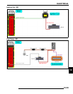
Armature Testing
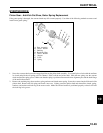
1. Remove armature from starter casing.
NOTE: Note order of shims on drive end for reassembly.
2. Inspect surface of commutator. Replace if excessively
worn or damaged.
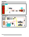
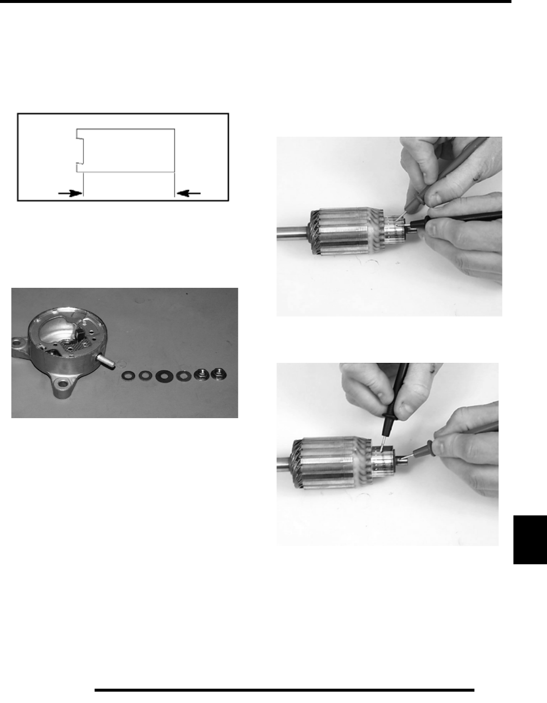
3. Using a digital multitester, measure the resistance between
each of the commutator segments. The reading should be
.3 ohms or less.
4. Measure the resistance between each commutator segment
and the armature shaft. The reading should be infinite (no
continuity).
5. Check commutator bars for discoloration. Bars discolored
in pairs indicate shorted coils, requiring replacement of the
starter motor.
6. Place armature in a growler. Turn growler on and position
a hacksaw blade or feeler gauge lengthwise 1/8” (.3 cm)
above armature coil laminates. Rotate armature 360
. If
hacksaw blade is drawn to armature on any pole, the
armature is shorted and must be replaced.
Limit 5/16” (8 mm)
Brush Length