


2-17190-01102-02 Rev. B
Garmin G500 Pilot’s Guide
Foreword
Sec 1
System
Sec 2
PFD
Sec 3
MFD
Sec 4
Hazard
Avoidance
Sec 5
Additional
Features
Sec 6
Annun.
& Alerts
Sec 7
Symbols
Sec 8
Glossary Appendix A
Appendix B
Index
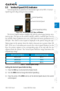
NOTE: The ILS Localizer and Glideslope deviation indicators will indicate
full-scale deflection for the GNS 480 navigator at the second dot. The GNS
400W/500W series navigators will indicate full-scale deflection at the edge
of the display.
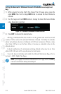
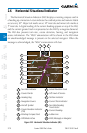
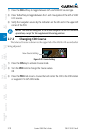
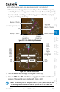
2.7.1 Changing CDI Sources
The CDI can display two sources of navigation: GPS or NAV (VOR, and LOC).
Color indicates the current navigation source: magenta (for GPS) or green (for
VOR and LOC). The full-scale limits for the CDI are defined by a GPS-derived
distance when coupled to GPS. When coupled to a VOR or localizer (LOC), the
CDI has the same angular limits as a mechanical CDI. If the CDI exceeds the
maximum deviation on the scale (two dots) while coupled to GPS, the crosstrack
error (XTK) is displayed below the white aircraft symbol.
GPS
Navigator 1
VLOC
Navigator 1
GPS
Navigator 2
VLOC
Navigator 2
Figure 2-27 CDI Navigation Sources