


4-70
Garmin G500 Pilot’s Guide
190-01102-02 Rev. B
Foreword
Sec 1
System
Sec 2
PFD
Sec 3
MFD
Sec 4
Hazard
Avoidance
Sec 5
Additional
Features
Sec 6
Annun.
& Alerts
Sec 7
Symbols
Sec 8
GlossaryAppendix A
Appendix B
Index
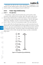
to 30 NM or closer. This is likely a thunderstorm that has a top high enough
that the aircraft cannot fly over it safely.
If the aircraft altitude is 15,000 feet or lower, set the displayed range to
60 NM. Closely monitor anything that enters the display.
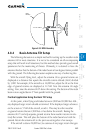
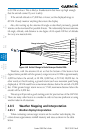
Also, after setting up the antenna tilt angle as described previously, ground
returns can be monitored for possible threats. The relationship between antenna
tilt angle, altitude, and distance is one degree of tilt equals 100 feet of altitude
for every one nautical mile.
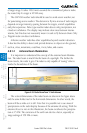
Vertical Change of Radar Beam (feet)
Change in Antenna Tilt
10 nm
0
1000
2000
3000
4000
1000
2000
3000
4000
-1°
0°
-2°
-3°
-4°
+1°
+2°
+3°
+4°
Figure 4-60 Vertical Change in Radar Beam per Nautical Mile
Therefore, with the antenna tilt set so that the bottom of the beam is four
degrees below parallel with the ground, a target return at 10 NM is approximately
4,000 feet below the aircraft; at 20 NM, 8,000 feet; at 50 NM, 20,000 feet. In
other words, at this tilt setting, a ground return (such as a mountain peak) being
displayed at 10 NM would have a maximum distance below the aircraft of 4,000
feet. If that ground target return moves to 5 NM, maximum distance below the
aircraft will be 2,000 feet.
This setup will provide a good starting point for practical use of the GWX 68.
There are many other factors to consider in order to become proficient at using
weather radar in all situations.
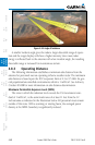
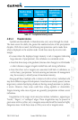
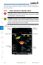
4.8.5 Weather Mapping and Interpretation
4.8.5.1 Weather display Interpretation
When evaluating various target returns on the weather radar display, the
colors denote approximate rainfall intensity and rates as shown in the table
below.