


2-16
Garmin G500 Pilot’s Guide
190-01102-02 Rev. B
Foreword
Sec 1
System
Sec 2
PFD
Sec 3
MFD
Sec 4
Hazard
Avoidance
Sec 5
Additional
Features
Sec 6
Annun.
& Alerts
Sec 7
Symbols
Sec 8
GlossaryAppendix A
Appendix B
Index
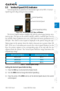
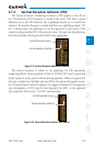
2.6.2 Turn Rate Indicator
The Turn Rate Indicator is located directly above the rotating compass card.
Tick marks to the left and right of the lubber line denote half-standard and
standard turn rates. A magenta Turn Rate Trend Vector shows the current turn
rate. The end of the trend vector gives the heading predicted in six seconds,
based on the present turn rate. A standard-rate turn is shown on the indicator
by the trend vector stopping at the standard turn rate tick mark, corresponding
to a predicted heading of 18º from the current heading. At rates greater than four
deg/sec, an arrowhead appears at the end of the magenta trend vector and the
prediction is no longer valid.
Turn Rate indication.
Arrowhead shown for a
Turn Rate > 4 deg/sec
½ Standard
Turn Rate
Standard Turn Rate
Current Track Indicator
Lubber Line
Heading Bug
Figure 2-25 Turn Rate Indicator and Trend Vector
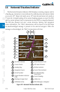
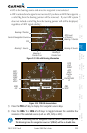
2.7 Course Deviation Indicator
The Course Deviation Indicator (CDI) moves left or right from the course
pointer along a lateral deviation scale to display aircraft position relative to the
course. If the course deviation data is not valid, the CDI is not displayed.
Crosstrack
Error
Scale
GPS Level
of Service
Navigation
Source
360º HSI
CDI
Figure 2-26 Course Deviation Indicator