


4-69190-01102-02 Rev. B
Garmin G500 Pilot’s Guide
Foreword
Sec 1
System
Sec 2
PFD
Sec 3
MFD
Sec 4
Hazard
Avoidance
Sec 5
Additional
Features
Sec 6
Annun.
& Alerts
Sec 7
Symbols
Sec 8
Glossary Appendix A
Appendix B
Index
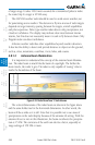
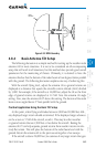
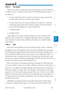
MPEL
Boundary
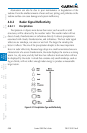
11’ for 12” antenna
Figure 4-59 MPEL Boundary
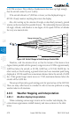
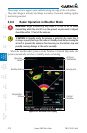
4.8.4 Basic Antenna Tilt Setup
The following discussion is a simple method for setting up the weather radar
antenna tilt for most situations. It is not to be considered an all encompassing
setup that will work in all situations, but this method does provide good overall
parameters for the monitoring of threats. Ultimately, it is desired to have the
antenna tilted so that the bottom of the radar beam is four degrees below parallel
with the ground. The following discussion explains one way of achieving this.
With the aircraft flying level, adjust the antenna tilt so ground returns are
displayed at a distance that equals the aircraft’s current altitude (AGL) divided
by 1,000. For example, if the aircraft is at 14,000 feet, adjust the tilt so the front
edge of ground returns are displayed at 14 NM. Note this antenna tilt angle
setting. Now, raise the antenna tilt 6º above this setting. The bottom of the radar
beam is now angled down 4º from parallel with the ground.
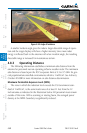
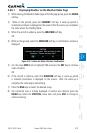
Practical Application Using the Basic Tilt Setup
At this point, when flying at altitudes between 2,000 and 30,000 feet AGL,
any displayed target return should scrutinized. If the displayed target advances
on the screen to 5 NM of the aircraft, avoid it. This may be either weather
or ground returns that are 2,000 feet or less below the aircraft. Raising the
antenna tilt 4º can help separate ground returns from weather returns in rela-
tively flat terrain. This will place the bottom of the radar beam level with the
ground. Return the antenna tilt to the previous setting after a few sweeps.
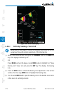
If the aircraft is above 29,000 feet, be cautious of any target return that gets