


2-6
Garmin G500 Pilot’s Guide
190-01102-02 Rev. B
Foreword
Sec 1
System
Sec 2
PFD
Sec 3
MFD
Sec 4
Hazard
Avoidance
Sec 5
Additional
Features
Sec 6
Annun.
& Alerts
Sec 7
Symbols
Sec 8
GlossaryAppendix A
Appendix B
Index
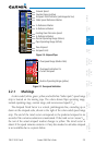
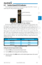
The horizon line is part of the pitch scale. Above and below the horizon line,
major pitch marks and numeric labels are shown for every 10º, up to 80º. Minor
pitch marks are shown for intervening 5º increments, up to 25º below and 45º
above the horizon line. Between 20º below to 20º above the horizon line, minor
pitch marks occur every 2.5º.
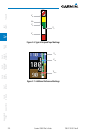
Major tick marks at 30º and 60º and minor tick marks at 10º, 20º, and 45º
are shown to the left and right of the zero. Angle of bank is indicated by the
position of the pointer on the roll scale.
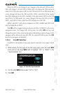
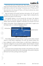
The Slip/Skid Indicator is the bar beneath the roll pointer. The indicator
moves with the roll pointer and moves laterally away from the pointer to
indicate lateral acceleration. Slip/skid is indicated by the location of the bar
relative to the pointer. One bar displacement (as shown below) is equal to one
ball displacement on a traditional Slip/Skid Indicator.
Roll Pointer
Slip/Skid Indicator
Roll Scale Zero
Figure 2-10 Slip/Skid Indication
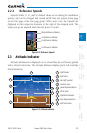
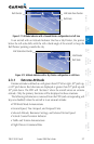
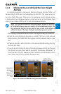
The standby mechanical Attitude Indicator in your aircraft is either a Ground
Pointer or a Roll Pointer configuration. The GDU 620 Attitude Indicator has
been configured in either a Ground Pointer or a Roll Pointer configuration to
match the configuration of your aircraft’s standby Attitude Indicator. Ground/
Sky Pointer mode is configured during installation and can not be changed by
the pilot.
In an aircraft with an Attitude Indicator that has a Ground Pointer, the pointer
above the Roll Scale shifts with the roll or bank angle of the aircraft to keep the
Roll Scale Zero Pointer pointing towards the ground.