


2-3190-01102-02 Rev. B
Garmin G500 Pilot’s Guide
Foreword
Sec 1
System
Sec 2
PFD
Sec 3
MFD
Sec 4
Hazard
Avoidance
Sec 5
Additional
Features
Sec 6
Annun.
& Alerts
Sec 7
Symbols
Sec 8
Glossary Appendix A
Appendix B
Index
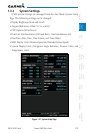
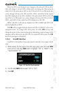
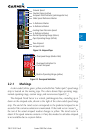
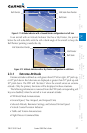
Ground Speed
Caution Range (yellow)
Airspeed Trend Indicator (pink/magenta line)
Glide Speed Reference Marker
Vr Reference Marker
Vx Reference Marker
Vy Reference Marker
Landing Gear Extension Speed
Normal Operating Range (Green)
Flaps Operating Range (White)
True Airspeed
Airspeed Units
Figure 2-4 Airspeed Tape
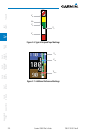
Overspeed Range (Barber Pole)
Overspeed Indication for
Current Airspeed
Caution Operating Range (yellow)
Figure 2-5 Overspeed Indication
2.2.1 Markings
A color-coded (white, green, yellow, and red/white “barber pole”) speed range
strip is located on the moving tape. The colors denote flaps operating range,
normal operating range, caution range, and never-exceed speed (V
NE
).
The Airspeed Trend Vector is a vertical, pink/magenta line, extending up or
down on the airspeed scale, shown to the right of the color-coded speed range
strip. The end of the trend vector corresponds to the predicted airspeed in six
seconds if the current acceleration is maintained. If the trend vector crosses V
NE
,
the text of the actual airspeed readout changes to yellow. The trend vector is
absent if the speed remains constant or if any data needed to calculate airspeed
is not available due to a system failure.