


1-2
Garmin G500 Pilot’s Guide
190-01102-02 Rev. B
Foreword
Sec 1
System
Sec 2
PFD
Sec 3
MFD
Sec 4
Hazard
Avoidance
Sec 5
Additional
Features
Sec 6
Annun.
& Alerts
Sec 7
Symbols
Sec 8
GlossaryAppendix A
Appendix B
Index
•GNS 480, CNX80, GNS 400W series, or GNS 500W series GPS
Navigator
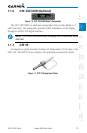
•Temperature Probe (such as the GTP 59)
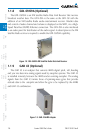
•GMU 44 Magnetometer
•GTX 330/330D TIS-B Traffic (optional)
•GDL 69A Satellite Data Link Receiver (optional)
•SL30 NavCom (optional)
•Autopilot/Flight Director (optional)
•ADF (optional)
•Traffic (optional: TAS and TIS)
•Audio Panel (optional)
•GAD 43 Adapter (optional)
•GWX 68 Weather Radar (optional)
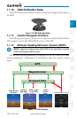
1.1.1 Line Replaceable Units (LRU)
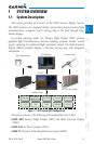
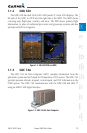
This guide covers the operation of the GDU 620 as integrated in the G500
system. The G500 Avionics Display System is an advanced technology avionics
suite designed to replace the traditional flight instrument cluster. The system
combines primary flight instrumentation, navigational information, and a moving
map all displayed on dual 6.5 inch color screens. The G500 system is composed
of sub-units or Line Replaceable Units (LRUs). LRUs have a modular design and
can be installed directly behind the instrument panel or in a separate avionics
bay if desired. This design greatly eases troubleshooting and maintenance of the
G500 system. A failure or problem can be isolated to a particular LRU, which
can be replaced quickly and easily. Each LRU has a particular function, or set of
functions, that contributes to the system’s operation.