


2-5190-01102-02 Rev. B
Garmin G500 Pilot’s Guide
Foreword
Sec 1
System
Sec 2
PFD
Sec 3
MFD
Sec 4
Hazard
Avoidance
Sec 5
Additional
Features
Sec 6
Annun.
& Alerts
Sec 7
Symbols
Sec 8
Glossary Appendix A
Appendix B
Index
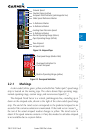
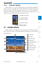
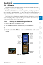
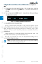
2.2.2 Reference Speeds
Vspeeds (Glide, V
r
, V
X
, and V
Y
) default values are set during the installation
process, but can be changed and turned on/off from the System Setup page
on the first page of the Aux page group. When active (on), the Vspeeds are
displayed at their respective locations to the right of the airspeed scale. The
values you set are retained when the unit power is cycled.
Glide Reference Marker
Vr Reference Marker
Vx Reference Marker
Vy Reference Marker
Figure 2-8 Reference Speeds
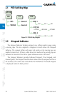
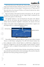
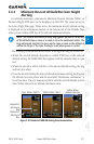
2.3 Attitude Indicator
Attitude information is displayed over a virtual blue sky and brown ground
with a white horizon line. The Attitude Indicator displays pitch, roll, and slip/
skid information.
1
Roll Pointer
2
Roll Scale
3
Aircraft Symbol
4
Horizon Line
5
Land Representation
6
Pitch Scale
7
Slip/Skid Indicator
8
Sky Representation
9
Roll Scale Zero
5
6
8
7
2
4
3
9
1
Figure 2-9 Attitude Indicator