


1-15190-01102-02 Rev. B
Garmin G500 Pilot’s Guide
Foreword
Sec 1
System
Sec 2
PFD
Sec 3
MFD
Sec 4
Hazard
Avoidance
Sec 5
Additional
Features
Sec 6
Annun.
& Alerts
Sec 7
Symbols
Sec 8
Glossary Appendix A
Appendix B
Index
1.2 System Power Up
NOTE: See the Aircraft Flight Manual (AFM) for specific procedures
concerning avionics power application and emergency power supply
operation.
NOTE: Refer to Section 6 for system-specific annunciations and alerts.
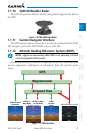
The G500 System is integrated with the aircraft electrical system and receives
power directly from electrical busses. The GDU 620 and supporting sub-systems
include both power-on and continuous built-in test features that exercise the
processor, memory, external inputs, and outputs to ensure safe operation.
During system initialization, test annunciations are displayed. All system
annunciations should disappear typically within the first 30 seconds after
power-up. Upon power-up, key annunciator lights also become momentarily
illuminated on the GDU 620 display bezel.
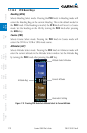
On the PFD, the AHRS begins to initialize and “AHRS ALIGN: Keep Wings
Level” is displayed. The AHRS should display valid attitude and heading fields
typically within the first minute after power-up. The AHRS can align itself both
while taxiing and during level flight.
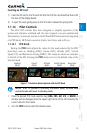
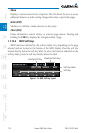
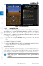
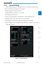
When the MFD powers up, the splash screen displays the following
information:
•Systemversion
•Copyright
•Landdatabasenameandversion
•Obstacledatabase name and version
•Terrain database name and version
•Aviationdatabasename,version,andeffectivedates
Current database information includes valid operating dates, cycle number,
and database type. When this information has been reviewed for currency (to
ensure that no databases have expired), the pilot is prompted to continue.