


8-11
Specifications
Process-Wetted Materials Meter Body
316L wrought stainless and CF-3M cast stainless or Hastelloy C-22
and C-276 wrought Hastelloy or CX2MW and CW12MW cast
Hastelloy.
Flanges
316/316L stainless steel.
Collars
Hastelloy C-22.
Surface Finish of Flanges and Collars
Standard: 125 to 250 in. (3.1 to 6.3 m) R
a
roughness.
Smooth: 63 to 125 in. (1.6 to 3.1 m) R
a
roughness.
Process Connections Mounts Between the Following Flange Configurations
• ASME B16.5 (ANSI): Class 150, 300, and 600.
• DIN: PN 10, 16, 25, 40, 64, and 100.
• JIS: 10K, 20K, and 40K.
Mounting Integral (Standard)
Electronics are mounted on meter body.
Remote (Optional)
Electronics may be mounted remotely from the meter body.
Interconnecting coaxial cable available in nonadjustable 10, 20, and
30 foot lengths (3.0, 6.1, and 9.1 m). Consult factory for nonstandard
lengths up to 75 feet (22.9 m). Remote mounting hardware includes
a polyurethane-painted, carbon steel pipe mount bracket with one
carbon steel u-bolt.
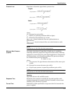
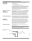
Pipe Length Requirements The vortex meter may be installed with a minimum of ten straight pipe
diameters (D) upstream and five downstream.
Rated accuracy is based on the number of pipe diameters from an
upstream disturbance. An additional 0.5% shift in K-factor may be
introduced between 10 D and 35 D, depending on disturbance. For more
information on installation effects, see Technical Data Sheet
00816-0100-3250.
Tagging A stainless steel tag is permanently attached to each flowmeter at no
charge. Character height is
1
/16 in. (1.6 mm). A wired-on tag is available
on request.
A commissioning tag, attached to each flowmeter, will aid in the
commissioning of the flowmeter on the fieldbus network by specifying the
identification number and the location of the flowmeter.
Flow Calibration Information Flowmeter calibration and configuration information is provided with
every flowmeter. For a certified copy of flow calibration data, an Option
Q4 must be ordered in the model number.