


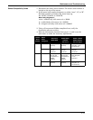
6-17
Maintenance and Troubleshooting
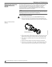
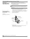
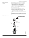
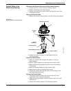
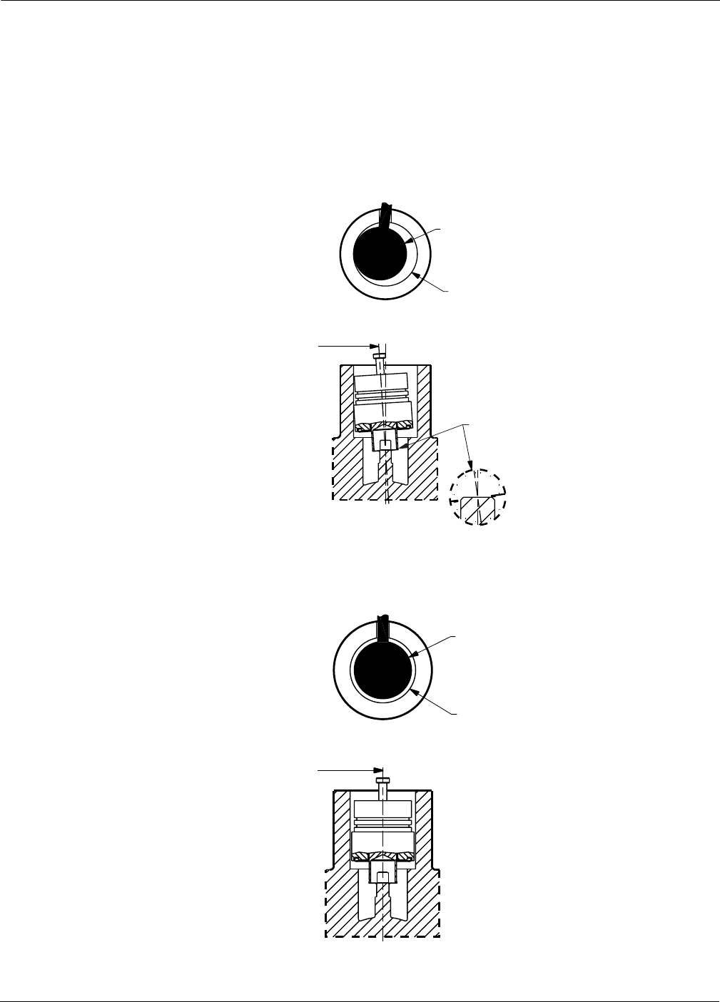
Sensor Installation
1. Carefully place sensor over the post in the sensor cavity.
2. Insure that the sensor is centered on the post. See Figure 6-13 for
an example of improper installation and Figure 6-14 for an
example of proper installation.
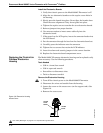
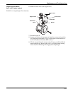
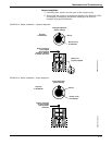
FIGURE 6-13. Sensor Installation – Improper Alignment.
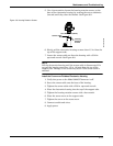
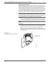
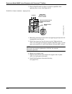
FIGURE 6-14. Sensor Installation – Proper Alignment.
Sensor
Sensor cavity
in flowmeter
Improper Alignment
(before seating)
Sensor not
properly aligned
Sensor centerline
is not aligned
with flowmeter
centerline. Damage
to sensor will occur.
Top View
of Flowmeter
SENSORS-sens05a
Proper Alignment
(before seating)
Sensor
Sensor cavity
in flowmeter
Sensor centerline
must be aligned
with flowmeter
centerline
Top View
of Flowmeter
SENSORS-sens05b