


Section
3-1
3 Flowmeter Operation
Section 3 covers basic operation, software functionality, and basic
configuration procedures for the Model 8800C Vortex Flowmeter with
F
OUNDATION fieldbus. For more information about the FOUNDATION
fieldbus technology and the function blocks used in the transmitter,
refer to Section 4: Transducer Block, Section 5: Resource Block,
Appendix A: Foundation™ fieldbus Technology and Fieldbus
Function Blocks, Appendix B: Analog Input (AI) Function Block, and
Appendix C: PID Function Block.
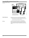
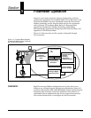
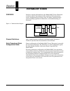
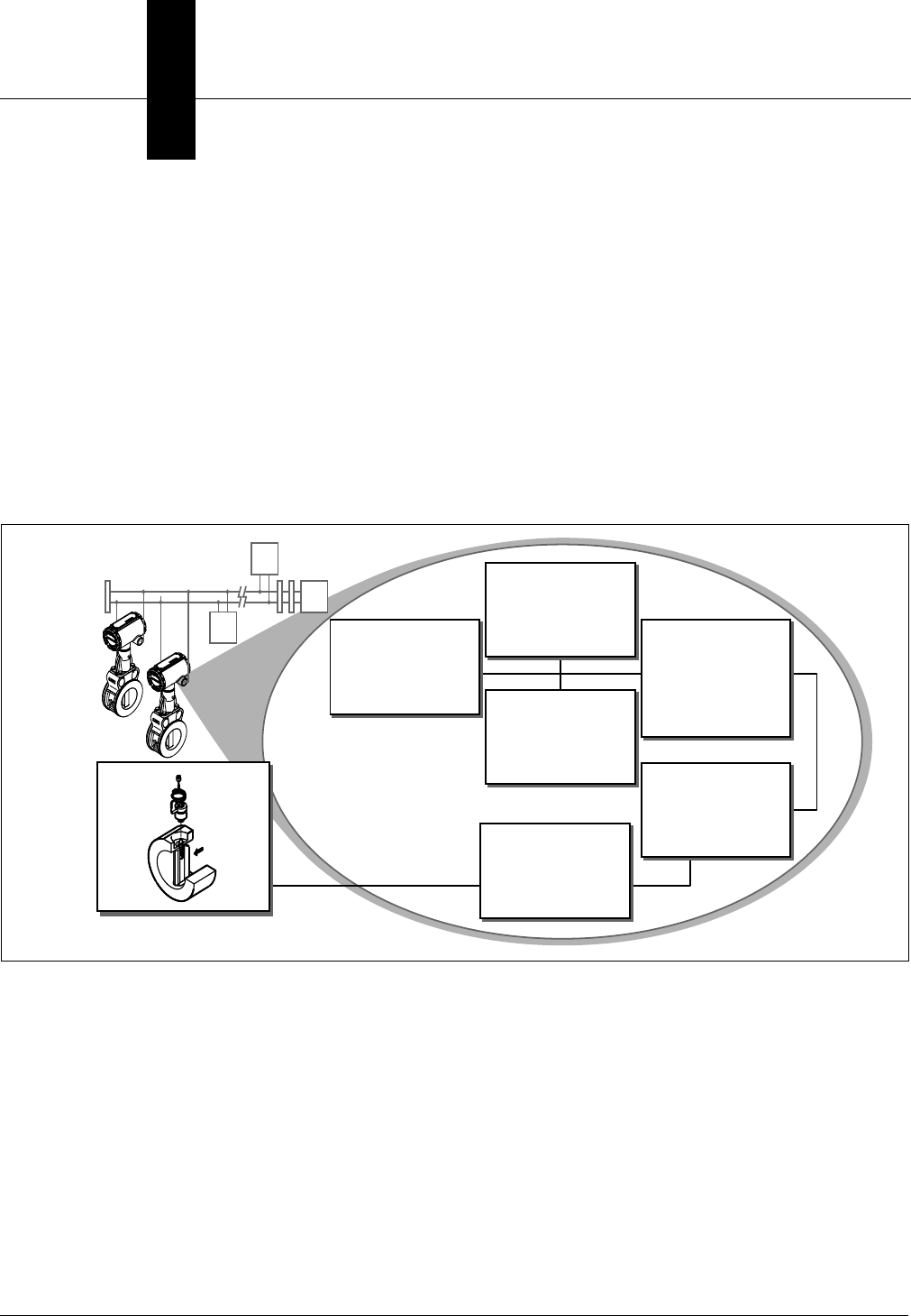
Figure 3-1 illustrates how the flow signal is channeled through
the transmitter.
Figure 3-1. Functional Block Diagram
for the Model 8800C Vortex Flowmeter
with F
OUNDATION Fieldbus.
OVERVIEW Each FOUNDATION fieldbus configuration tool or host device has a
different way of displaying and performing configurations. Some will
use Device Descriptions (DD) and DD Methods to make configuring and
displaying data consistent across host platforms. Since there is no
requirement that a configuration tool or host support these features,
this section describes how to reconfigure the device manually.
Analog-to-Digital
Signal Conversion
Input-to-Output
Galvanic Isolation
Transducer Block
• Rerange
• Damping
• Diagnostics
• Engineering Units
Function Blocks
•AI
•PID
Resource Block
• Physical Device
Information
F
OUNDATION fieldbus
Compliant
Communications
Stack
Vortex Shedding
8800-8800_02A