


6-5
Maintenance and Troubleshooting
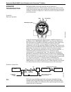
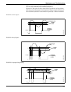
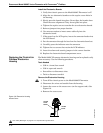
TP1 is easily measured with standard equipment.
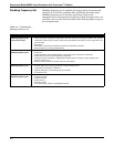
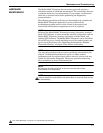
Figures 6-3, 6-4, and 6-5 show ideal (clean) waveforms and waveforms
that may cause the output to be inaccurate. Please consult the factory if
the waveform you detect is not similar in principle to these waveforms.
FIGURE 6-3. Clean Signals.
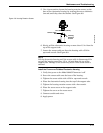
FIGURE 6-4. Noisy Signals.
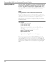
FIGURE 6-5. Improper Sizing/Filtering.
Trigger
Level
8800-0572A
Vortex Signal (TP1)
Shedding
Frequency
Output
0
3.45 V
0
8800-0572B
Vortex Signal
(TP1)
Trigger
Level
Shedding
Frequency
Output
0
3.45 V
0
8800-0572C
Shedding
Frequency
Output
0
3.45 V
0
Vortex Signal
(TP1)
Trigger
Level