


Rosemount Model 8800C Vortex Flowmeter with FOUNDATION
™
Fieldbus
2-2
Flowmeter Orientation Design process piping so the meter body will remain full, with no
entrapped air. Allow enough straight pipe both upstream and
downstream of the meter body to ensure a nonskewed, symmetrical
profile. Install valves downstream of the meter when possible.
Vertical Installation Vertical installation allows upward process liquid flow and is generally
preferred. Upward flow ensures that the meter body always remains
full and that any solids in the fluid are evenly distributed.
The vortex meter can be mounted in the vertical down position when
measuring gas or steam flows. This type of application should be
strongly discouraged for liquid flows, although it can be done with
proper piping design.
NOTE
To ensure that the meter body remains full, avoid downward vertical
liquid flows where back pressure is inadequate.
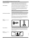
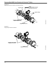
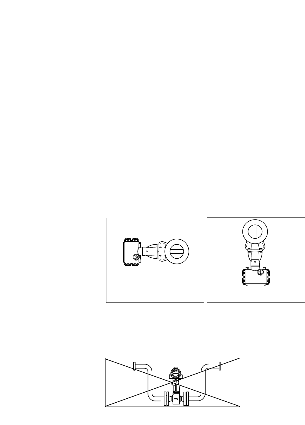
High-Temperature Installations Install the meter body so the electronics are positioned to the side of
the pipe or below the pipe, as shown in Figure 2-1. Insulation may be
required around the pipe to maintain a temperature below 185 °F
(85 °C).
When insulating, the insulation should be made only around the pipe
and meter body. Leave part of the support tube bracket exposed to
ambient environment for both remote and integral installations. This
aids in dissipating the heat from the process.
Figure 2-1.
Examples of High-Temperature
Installations.
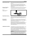
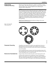
Steam Installations For steam applications, avoid installations such as the one shown in
Figure 2-2. Such installations may cause a water-hammer condition at
start-up due to trapped condensate. The high force from the water
hammer can overstress the sensing mechanism and cause permanent
damage to the sensor.
Figure 2-2.
Avoid This Type of Installation for
Steam Applications.
The meter body installed with the
electronics to the side of the pipe.
The meter body installed with the
electronics below the pipe.
8800-0002A01C8800-8800G15