


4-5
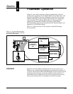
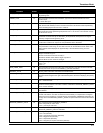
Transducer Block
LFC_IN_ENG_UNITS 44 This read-only parameter will indicate Low Flow Cutoff in currently configured
engineering units.
LINEAR_TYPE 27 This parameter represents the linearization type used to describe the behavior of the
sensor output.
1 = linear with input
LOW_FLOW_CUTOFF 43 The low-flow cutoff (LFC) represents the minimum reportable flow rate. For flow below this
rate, the flow rate will damp to zero. The rate can be set to 48 discrete values representing
vortex shedding frequencies from 0.9 to 4160 Hz.
LOW_PASS_CODE 42 The low pass code setting determines the corner frequency of the digital low pass filter. There
are 29 discrete values representing frequencies from 0.1 to 3414 Hz. The code has a range
of values from 2 to 30.
MAX_SIM_VALUE 67 This is the maximum simulation value that the internal signal can supply. The units for this
parameter are determined by the Simulation_Units parameter, either percent of range or
currently configured PV Engineering Units.
METER_BODY_NUMBER 40 The meter body number is stamped on a tag attached to the meter body. The meter body
construction is used as an input to the compensated K-factor calculation.
METER_DISPLAY 41 This parameter is used to configure the values that will be displayed on the LCD (if installed).
This parameter is a bit string, so more than one item can be selected at a time. Each of the
items selected will be displayed for approximately 3 seconds before moving on to the
next item.
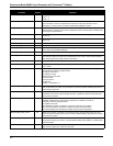
MODE_BLK 5 The actual, target, permitted, and normal modes of the block:
Target: The mode “to go to”
Actual: The mode the “block is currently in”
Permitted: Allowed modes that the target may take on
Normal: Most common mode for the target
PIPE_ID_UNITS 39 The engineering units of the mating pipe inside diameter:
1013 = mm
1019 = in.
PIPE_INSIDE_DIAM 38 This parameter represents the mating pipe inside diameter. This value is used to calculate
velocity flow and as an input to the COMPD_K_FACTOR calculation.
PRIMARY_VALUE 14 Primary value is the value and status of the measurement.
PRIMARY_VALUE_RANGE 15 This parameter represents the high and low range limit values, the engineering units code,
and the number of digits to the right of the decimal point to be used in displaying the primary
value.
PRIMARY_VALUE_TYPE 13 The primary value type is the type of measurement represented by the primary value.
101 = Volumetric Flow
PROCESS_COMPRESSIBILITY 60 Process compressibility is the compressibility of the process fluid at the process conditions of
pressure and temperature. This value is used to calculate the PROCESS_DENSITY_RATIO
and is not limit checked.
PROCESS_DENSITY 49 The configured density of the process fluid is used to calculate flow when mass units
are selected.
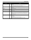
PROCESS_DENSITY_RATIO 61 This parameter is the process density ratio used in the conversion to standard cubic feet and
normal cubic meters. The ratio can either be entered directly or computed from configured
base and process conditions. If entered directly, the PROCESS_PRESSURE parameter will
change so that the PROCESS_DENSITY_RATIO computed value is the same as the entered
value.
PROCESS_DENSITY_UNITS 50 The engineering units of PROCESS_DENSITY:
1097 = kilograms per cubic meter
1107 = pounds per cubic foot
PROCESS_PRESSURE 58 Process pressure is the operating pressure of the process fluid upon which the
PROCESS_DENSITY_RATIO is calculated.
PROCESS_PRESSURE_UNITS 59 The engineering units of process pressure:
1137 = bar (absolute)
1142 = pounds per square inch (absolute)
1545 = Megapascals (absolute)
1547 = Kilopascals (absolute)
1557 = Kilograms per square centimeter (absolute)
Parameter
Index
Number
Definition