


Rosemount Model 8800C Vortex Flowmeter with FOUNDATION
TM
Fieldbus
C-6
Setpoint Selection
and Limiting
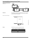
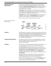
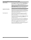
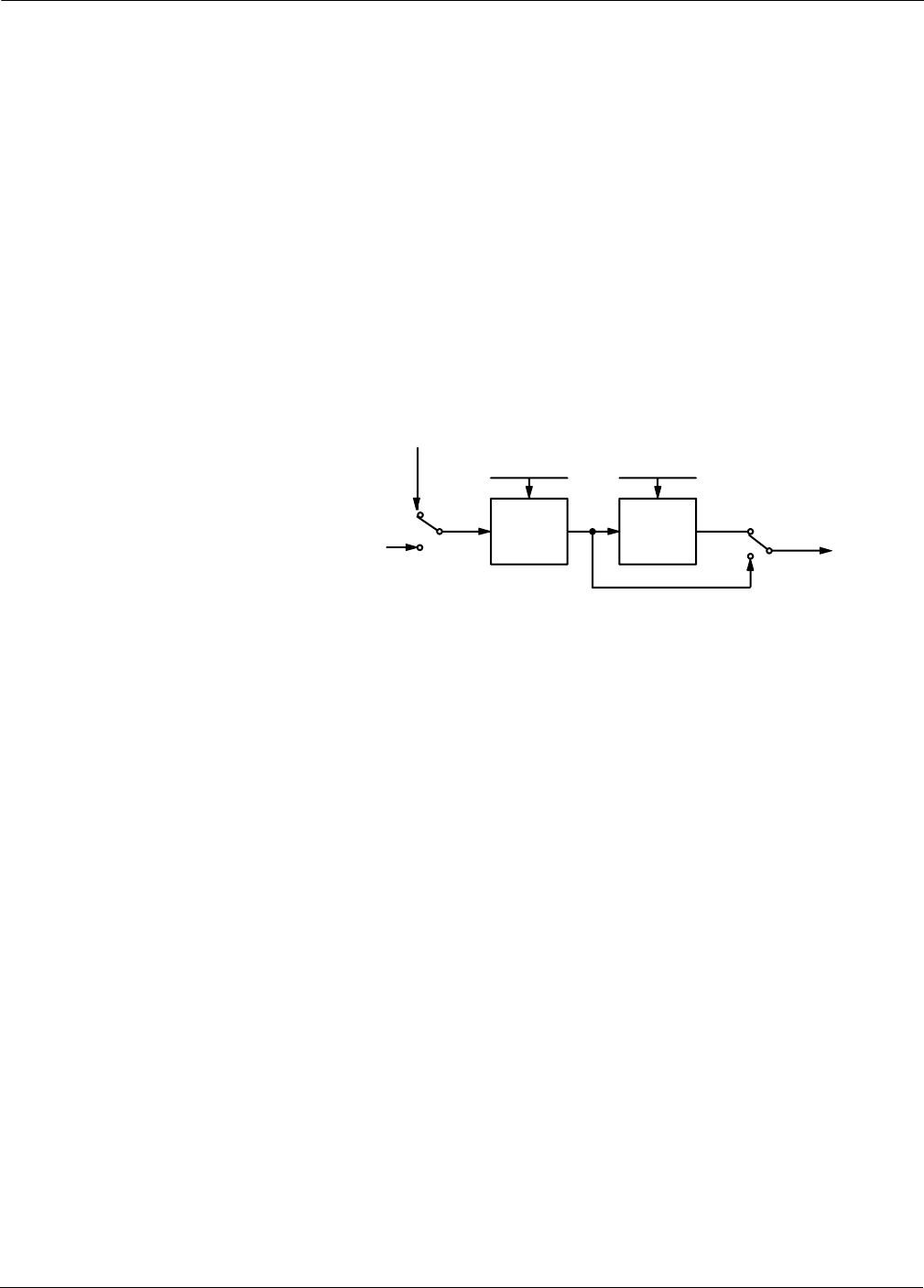
The setpoint of the PID block is determined by the mode. You can
configure the SP_HI_LIM and SP_LO_LIM parameters to limit the
setpoint. In Cascade or RemoteCascade mode, the setpoint is adjusted
by another function block or by a host computer, and the output is
computed based on the setpoint.
In Automatic mode, the setpoint is entered manually by the operator,
and the output is computed based on the setpoint. In Auto mode, you
can also adjust the setpoint limit and the setpoint rate of change using
the SP_RATE_UP and SP_RATE_DN parameters.
In Manual mode the output is entered manually by the operator, and is
independent of the setpoint. In RemoteOutput mode, the output is
entered by a host computer, and is independent of the setpoint.
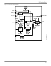
Figure C-2 illustrates the method for setpoint selection.
Figure C-2. PID Function Block
Setpoint Selection.
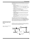
Filtering The filtering feature changes the response time of the device to smooth
variations in output readings caused by rapid changes in input. You can
configure the filtering feature with the FILTER_TYPE parameter, and
you can adjust the filter time constant (in seconds) using the
PV_FTIME or SP_FTIME parameters. Set the filter time constant to
zero to disable the filter feature.
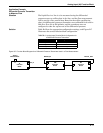
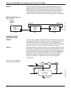
Feedforward Calculation The feedforward value (FF_VAL) is scaled (FF_SCALE) to a common
range for compatibility with the output scale (OUT_SCALE). A gain
value (FF_GAIN) is applied to achieve the total
feedforward contribution.
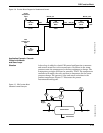
Tracking You enable the use of output tracking through the control options. You
can set control options in Manual or Out of Service mode only.
The Track Enable control option must be set to True for the track
function to operate. When the Track in Manual control option is set to
True, tracking can be activated and maintained only when the block is
in Manual mode. When Track in Manual is False, the operator can
override the tracking function when the block is in Manual mode.
Activating the track function causes the block’s actual mode to revert to
Local Override.
The TRK_VAL parameter specifies the value to be converted and
tracked into the output when the track function is operating. The
TRK_SCALE parameter specifies the range of TRK_VAL.
When the TRK_IN_D parameter is True and the Track Enable control
option is True, the TRK_VAL input is converted to the appropriate
value and output in units of OUT_SCALE.
Operator
Setpoint
SP_HI_LIM
SP_LO_LIM
SP_RATE_UP
SP_RATE_DN
Setpoint
Limiting
Rate
Limiting
Auto
Man
Auto
Man
Cas
Cas
FIELDBUS-FBUS_01A