


Rosemount Model 8800C Vortex Flowmeter with FOUNDATION
™
Fieldbus
6-2
TROUBLESHOOTING
TABLES
The most common problems experienced by users of the Model 8800C
Flowmeter are listed in Table 6-1, along with potential causes of the
problem and suggested corrective actions. See live if the problem you
are experiencing is not listed here.
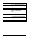
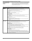
TABLE 6-1. Basic Troubleshooting—Model 8800C Vortex Flowmeter with FOUNDATION Fieldbus
Symptom Corrective Action
Flow in Pipe,
No Output
Basics
• Check to make sure that the meter is installed with the arrow in the direction of flow.
• Check and correct configuration parameters in this order: K-factor, service type, materials, units, process
temperature, damping value, density, pipe diameter, LRV, URV, trigger level, low-flow cutoff.
• Check sizing. Make sure flow is within measurable flow limits.
• Refer to live.
• See Section 9: Electronics Verification for electronics verification procedure.
Electronics
• Using sensor simulator, insert test signal.
• Check configuration, LFC, trigger level, STD vs. actual flow.
• Replace electronics.
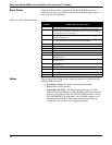
Application Problems
• Calculate expected frequency (see Section 9: Electronics Verification). If actual frequency is the same, check
configuration.
• Check that application meets viscosity and specific gravity requirements for the line size.
• Recalculate back pressure requirement. If necessary and possible, increase back pressure, flow rate, or
operating pressure.
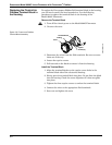
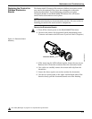
Sensor
• Check torque on sensor nut (32 ft-lb).
• Inspect coaxial sensor cable for cracks. Replace if necessary.
• Check that sensor impedance >10 Megaohms. Replace the sensor if necessary (see “Replacing the Sensor”
on page 6-12).
• Measure sensor capacitance at SMA connector (100–200pF).
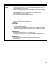
Flow in Pipe,
Incorrect Output
Basics
• Check and correct configuration parameters in this order: K-factor, service type, materials, units, process
temperature, damping value, density, pipe diameter, LRV, URV, trigger level, and low-flow cutoff.
• Check sizing. Make sure flow is within measurable flow limits.
• Refer to live.
• See Section 9: Electronics Verification for electronics verification procedure.
Application Problems
• Calculate expected frequency. If actual frequency is the same, check configuration.
• Check to make sure the meter is not installed backwards (if the arrow on the meter is pointing upstream, then
the meter is installed backwards). Re-install the meter if necessary.
• Check that application meets viscosity and specific gravity requirements for the line size.
• Recalculate back pressure requirement. If necessary and possible, increase back pressure, flow rate, or operating
pressure.
• Check for gasket or other obstruction disturbing flow. Reinstall meter if necessary.
• Check if pump pulsations are disturbing flow. Adjust signal processing parameters.
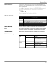
Vibration Problem
• Adjust signal processing parameters.
• Rotate meter 90°.
• Add support to the line near the meter to damp the vibration.
When the vortex meter is set for gas or steam service and the vibration levels are greater than ½ g, the
low-flow cutoff value (LFC) may need to be increased to eliminate undesirable output at no flow conditions. The
level of LFC increase depends on the vibration level and meter size. LFC is unique for each application. When
flow begins, the flow signal becomes much larger than the vibration signal and the meter will lock onto the flow
signal and give an accurate flow output.