I-5
Index
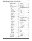
Cleaning the Sensor Sealing
Surface
.................... 6-16
Removable Support Tube ...... 6-14
Sensor Serial Number ..........4-11
Sensor Signal Strength ......... 4-14
Service Type ...............4-11,4-13
Setpoint selection
PID block ....................C-6
Setpoint tracking ................C-7
Setup
basic ....................... 4-11
Shedding Frequency Out ......... 6-6
Signal conversion
direct ........................B-5
indirect ......................B-5
Signal Strength ................4-14
Simulate switch ................. 2-4
Simulation ......................B-3
jumper ......................B-3
Simulator mode ................. 2-4
Software Configuration
Basic Steps .................. 2-22
SP_FTIME
PID block ....................C-6
SP_HI_LIM
PID block ....................C-6
SP_LO_LIM
PID block ....................C-6
SP_RATE_DN
PID block ....................C-6
SP_RATE_UP
PID block ....................C-6
SP_WRK
PID block ....................C-7
Specifications
Foundation Fieldbus ........... 8-8
Standard/Normal Flow Units .... 4-10
Status
AI block ......................B-7
Status handling
PID block ...................C-10
STRUCTURE
PID block ....................C-7
Subscriber (S) ...................A-5
Switches
simulate ..................... 2-4
System management .............A-2
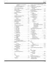
T
Tag
definition ....................A-2
device ....................... 3-2
Tagging ........................ 2-22
Target to Manual if Bad IN mode .C-10
Temperature ...................4-11
Temperature specific block
configuration
AI block ......................3-2
Terminal Block Replacement ......6-8
Track Enable ....................C-6
Track in Manual .................C-6
Tracking
PID block .....................C-6
Transducer Block
description ...................4-11
Transducer block ................4-1
configuration
general
...................3-3
definition .....................A-3
modes ......................4-15
parameters
all
.......................4-4
BLOCK_ERR ..............4-8
ELECTRONICS_STATUS ...4-9
MODE_BLK ..............4-15
XD_ERROR ...............4-8
troubleshooting ...............4-10
Transmitter Security Switch ......2-4
TRK_IN_D
PID block .................C-1,C-6
TRK_VAL
PID block .................C-1,C-6
Troubleshooting
AI block .....................B-12
PID block ....................C-16
resource block .................5-5
transducer block ..............4-10
Troubleshooting Tables ...........6-2
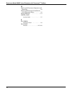
U
Units
flow ........................4-11
simulation ...................4-16
Unsupported options .............C-8
Upload ..........................A-6
Upstream/Downstream Piping ....2-2
V
VAR_INDEX
AI block ......................B-8
VAR_SCAN
AI block ......................B-8
VCR ........................ 5-5,8-8
Vertical Installation ..............2-2
Virtual Communications
Relationships ..................5-5
Volumetric Flow ................4-11


