


Rosemount Model 8800C Vortex Flowmeter with FOUNDATION
™
Fieldbus
4-6
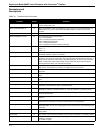
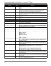
PROCESS_TEMP_UNITS 52 The engineering units of process temperature:
1001 = °C
1002 = °F
PROCESS_TEMPERATURE 51 Process temperature is the configured temperature of the process fluid, in units of °C or °F.
This parameter is used to compensate the K-factor for meter body expansion due to
temperature. It is also used to calculate the PROCESS_DENSITY_RATIO.
REQ_PROC_DENSITY 48 This read-only parameter indicates the minimum required process density for proper flow
measurement. It is based on the current configuration of the Low Flow Cutoff, Low Pass Filter,
and Trigger Level parameters.
SECONDARY_VALUE 28 This parameter represents the secondary value related to the sensor (e.g., Vortex Shedding
Frequency).
SECONDARY_VALUE_UNIT 29 The engineering units to be used with SECONDARY_VALUE:
1077 = Hz.
SENSOR_CAL_DATE 25 Sensor call date is the last date on which the calibration was performed.
SENSOR_CAL_LOC 24 This parameter specifies the location of the last sensor calibration.
SENSOR_CAL_METHOD 23 The last method used to calibrate the device (e.g., factory calibration or user specific):
103 = factory trim standard calibration
SENSOR_CAL_WHO 26 This parameter specifies the name of the person responsible for the last sensor calibration.
SENSOR_RANGE 21 Sensor range specifies the high and low range limit values, the engineering units code, and
the number of digits to the right of the decimal point for the sensor. These values represent
the nominal high and low range values for the sensor.
SENSOR_SN 22 SENSOR_SN is the serial number of the sensor.
SENSOR_TYPE 20 The type of sensor on input #1:
112 = Vortex
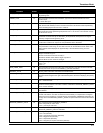
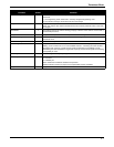
SERVICE_TYPE 35 Service type is the type of fluid being measured, either gas/steam or liquid. Changing service
type will set the following to default values:
PV Range 100% Value
PV Range 0% Value
Sensor Range 100% Value
Low-Pass Code
Low-Flow Cutoff
Trigger level
Liquid = 0, Gas/Steam = 1
SHEDDING_FREQ_AT_URV 68 This read-only parameter represents the Vortex Shedding Frequency required to generate a
flow at 100% of the PV range. It is provided as an aid to the operator simulating flow with an
external signal generator.
SIGNAL_STRENGTH 47 This parameter represents the relative sensor signal strength. A properly configured
transmitter should have a signal strength value of 4 or greater for all flow rates greater than
the low-flow cutoff point.
SIMULATION_CONTROL 66 This parameter is used to control transducer block flow simulation. Simulation can be
disabled, enabled using an internal signal generator or enabled for use with an
externally-conencted signal generator.
Acceptable values are:
Sim Disabled: Simulation is disabled, normal flow measurement is enabled.
Sim-Internal Generator: Simulation is enabled using the internal generator.
Sim-External Generator: Simulation is enabled using the external generator.
SIMULATION_HIGH_POINT 63 When flow simulation is enabled in the transducer block, this will configure the high point
when the signal is ramping up and down. If equal to SIMULATION_LOW_POINT, a constant
value will be simulated.
SIMULATION_LOW_POINT 64 When flow simulation is enabled in the transducer block, this will configure the low point when
the signal is ramping up and down. If equal to SIMULATION_HIGH_POINT, a constant value
will be simulated.
SIMULATION_RAMP_PERIOD 65 When flow simulation is enabled, this will configure the time for the signal to ramp from low to
high, and from high to low. Units are in seconds.
Parameter
Index
Number
Definition