


2-7
Installation
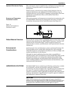
Wafer-Style Flowmeter
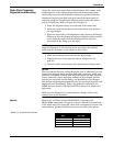
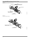
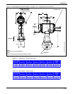
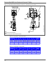
Alignment and Mounting
Center the wafer-style meter body inside diameter with respect to the
inside diameter of the adjoining upstream and downstream piping,
which will ensure that the flowmeter achieves its specified accuracy.
Alignment rings are provided with each wafer-style meter body for
centering purposes. Complete the following steps to align the meter
body for installation. Refer to Figure 2-6 on page 2-8.
1. Place the alignment rings over each end of the meter body.
2. Insert the studs for the bottom side of the meter body between
the pipe flanges.
3. Place the meter body (with alignment rings) between the flanges.
Make sure that the alignment rings are properly placed onto the
studs. Align the studs with the markings on the ring that
correspond to the flange you are using.
NOTE
Align the flowmeter so the electronics are accessible, the conduits
drain, and the flowmeter is not subject to direct heat.
4. Place the remaining studs between the pipe flanges.
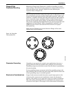
5. Tighten the nuts in the sequence shown in Figure 2-8 on
page 2-9.
6. Check for leaks at the flanges after tightening the flange bolts.
NOTES
The required bolt load for sealing the gasket joint is affected by several
factors, including operating pressure and gasket material, width, and
condition. A number of factors also affect the actual bolt load resulting
from a measured torque, including condition of bolt threads, friction
between the nut head and the flange, and parallelism of the flanges.
Due to these application-dependent factors, the required torque for each
application may be different. Follow the guidelines outlined in the
ASME Pressure Vessel Code (Section VIII, Division 2) for proper bolt
tightening.
Make sure the flowmeter is centered between flanges of the same
nominal size as the flowmeter.
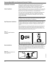
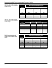
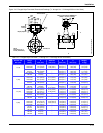
Spacers Spacers are available with the Model 8800C to maintain the
Model 8800A dimensions. If a spacer is used, it should be downstream
of the meter body. The spacer kit comes with an alignment ring for ease
of installation. Gaskets should be placed on each side of the spacer.
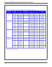
TABLE 2-4. Dimensions for Spacers.
Line
Size
Dimensions
inch (mm)
1.5 (40) 0.47 (11.9)
2 (50) 1.17 (29.7)
3 (80) 1.27 (32.3)
4 (100) 0.97 (24.6)