


9-5
Electronics Verification
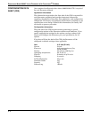
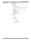
To Verify a Mass Flow Rate
Perform the following calculation to verify a mass flow rate for a given
mass frequency and K-factor (compensated).
Conditions:
•M = flow rate
• F = frequency, measured in Hz
• K = K-factor (compensated)
• ρ = density at operating conditions
• C = the unit conversion
Equation:
Conditions:
•C
x
= the unit conversion using density (ρ) (see Table 9-1 on
page 9-6)
Equation:
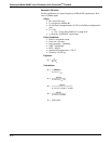
User Defined Verification
Frequencies
If a larger range of test frequencies is desirable, then use the test points
at the top of the electronics board.
1. Remove the LCD cover (if applicable).
2. Remove the two screws and the LCD indicator (if applicable).
3. Unscrew and remove the electronics compartment cover.
4. Remove the sensor from the electronics.
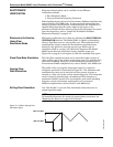
5. Connect the sinewave generator to the Test Frequency In and
Chassis Ground points as shown in Figure 9-2.
6. Set the sinewave generator amplitude to 2Vpp ±10%.
7. Connect a F
OUNDATION fieldbus configurator to the loop.
8. Access the AI output of the transmitter on the F
OUNDATION
fieldbus configurator.
9. Calculate the output frequency using the procedure on page 9-4.
10. Check the shedder frequency on the communicator display, the
calculated frequency, and the input frequency at each of the
following points: 0%, 25%, 50%, 75%, and 100%.
11. If the frequencies match within ±0.025mA, the output is verified.
12. Reconnect the sensor. Be sure to carefully align the connector
before inserting it.
13. Reconnect the LCD indicator option (if applicable) to the
electronics board by replacing and tightening the two screws.
14. Replace and tighten the electronics compartment cover.
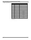
Unit Conversion Table (User Units to GPS)
Use the following table to assist with calculated frequencies when using
user-defined units.
M
F
K
⁄
C
×
-------------------=
M
F
KC
x
×
---------------
=