


2-5
Installation
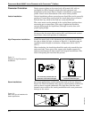
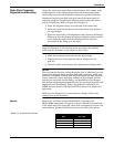
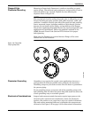
LCD Indicator Option If your electronics are equipped with the LCD indicator (Option M5),
the fieldbus simulate enable and transmitter security jumpers are
located on the face of the indicator as shown in Figure 2-5.
Figure 2-5. LCD Indicator Fieldbus
Simulate Enable and Transmitter
Security Jumpers.
INSTALLATION TASKS The installation tasks include detailed mechanical and electrical
installation procedures.
Handling Handle all parts carefully to prevent damage. Whenever possible,
transport the system to the installation site in the original shipping
containers. Keep the shipping plugs in the conduit connections until
you are ready to connect and seal them.
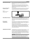
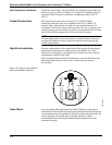
Flow Direction Mount the meter body so the FORWARD end of the flow arrow, shown
on the meter body, points in the direction of the flow through the body.
Gaskets The Model 8800C Flowmeter requires gaskets supplied by the user. Be
sure to select gasket material that is compatible with the process fluid
and pressure ratings of the specific installation.
NOTE
Ensure that the inside diameter of the gasket is larger than the inside
diameter of the flowmeter and adjacent piping. If gasket material
extends into the flow stream, it will disturb the flow and cause
inaccurate measurements.
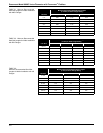
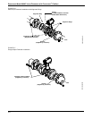
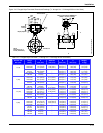
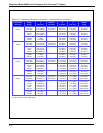
Flange Bolts Install the Model 8800C Flowmeter between two conventional pipe
flanges, as shown in Figure 2-6 and Figure 2-7 on page 2-8. Table 2-1,
Table 2-2, and Table 2-3 list the recommended minimum stud bolt
lengths for wafer-style meter body size and different flange ratings.
8800-0000B04B