


Rosemount Model 8800C Vortex Flowmeter with FOUNDATION
TM
Fieldbus
9-2
ELECTRONICS
VERIFICATION
Electronics functionality can be verified via two different
verification methods:
• Flow Simulation Mode
• Using an External Frequency Generator
Both methods require the use of a F
OUNDATION fieldbus-compliant host,
such as DeltaV with AMSinside. It is not required to disconnect the
sensor to perform the electronics verification since the transmitter is
capable of disconnecting the sensor signal at the input to the
electronics. Should the user choose to physically disconnect the sensor
from the electronics, refer to “Install the Foundation Fieldbus
Electronics Housing” on page 6-11.
Electronics Verification
Using Flow
Simulation Mode
Electronics verification can be done by utilizing the SIM-INTERNAL
GENERATOR function. The Model 8800C is capable of simulating
either a fixed flow rate or a varying flow rate. The amplitude of the
simulated flow signal is based on the minimum required process
density for the given line size and service type. Either type of
simulation (fixed or varying) will effectively disconnect the Model
8800C sensor from the electronics charge amplifier input (see
Figure 6-2 on page 6-4) and replace it with the simulated flow signal.
Fixed Flow Rate Simulation
The fixed flow simulation signal can be entered in either percent of
range or flow rate in the current engineering units. The resulting flow
rate and/or shedding frequency can be continuously monitored via a
F
OUNDATION fieldbus-compliant host, such as DeltaV with AMSinside.
Varying Flow
Rate Simulation
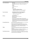
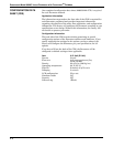
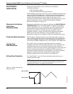
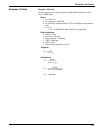
The profile of the varying flow simulation signal is a repetitive
triangular waveform as illustrated in Figure 9-1. The minimum and
maximum flow rates can be entered in either percent of range or
entered as a flow rate in the current engineering units. The ramp time
can be entered in seconds from a minimum of 0.533 seconds to a
maximum of 34951 seconds. The resulting flow rate and/or shedding
frequency can be continuously monitored via a F
OUNDATION
fieldbus-compliant host, such as DeltaV with AMSinside.
Exiting Flow Simulation Use “Sim Disable” to exit the flow simulation mode and return to
normal operation mode.
NOTE
To manually disconnect the sensor for precautionary measures, see
“Replacing the Sensor” on page 6-12 for details.
Figure 9-1. Profile of Varying Flow
Simulation Signal.
Max Flow Rate
Min Flow Rate
Ramp Time
8800-0000A04C