


2-21
Installation
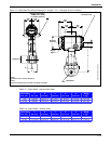
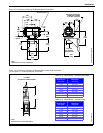
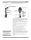
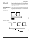
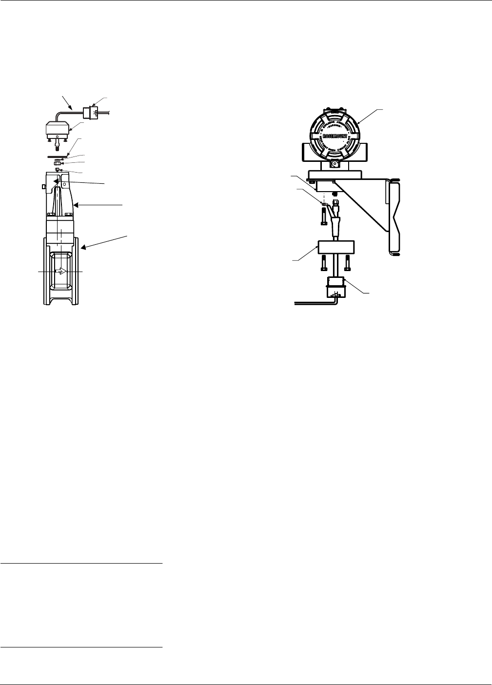
Cable Connections Refer to Figure 2-18 and the following instructions to connect the loose
end of the coaxial cable to the electronics housing.
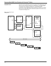
Figure 2-18. Remote Electronics Installation.
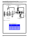
1. If you plan to run the coaxial cable in conduit, carefully cut the
conduit to the desired length to provide for proper assembly at
the housing. A junction box may be placed in the conduit run to
provide a space for extra coaxial cable length.
2. Slide the conduit adapter or cable gland over the loose end of
the coaxial cable and fasten it to the adapter on the meter body
support tube.
3. If using conduit, route the coaxial cable through the conduit.
4. Place a conduit adapter or cable gland over the end of the
coaxial cable.
5. Remove the housing adapter from the electronics housing.
6. Slide the housing adapter over the coaxial cable.
7. Remove one of the four housing base screws.
8. Bend the round lug so it is perpendicular to the cable.
9. Attach and securely tighten the coaxial cable nut to the
connection on the electronics housing.
10. Attach the coaxial cable ground connection round lug to the
housing via the housing base ground screw. Use the 1
1
/2-inch
screw to go through the round lug and attach to the housing base.
11. Align the housing adapter with the housing and attach with
three screws.
12. Tighten the conduit adapter or cable gland to the housing
adapter.
Electronics Housing
Ground Connection
Housing Adapter
Optional ½–14 NPT
Conduit Adapter or
Cable Gland
(Supplied by
Customer)
Mounting
Bracket for
Wall or
2-Inch Pipe
Coaxial Cable
Meter Adapter
Meter Body
Optional ½–14 NPT Conduit Adapter
or Cable Gland (Supplied by Customer)
Union
Sensor Connection
Access Cover
Support Tube
Washer
Nut
8800-0470A02B, 0470A01B
Coaxial Cable
Housing Base
CAUTION
To prevent moisture from entering
the coaxial cable connections,
install the interconnecting coaxial
cable in a single dedicated conduit
run or use sealed cable glands at
both ends of the cable.