


Rosemount Model 8800C Vortex Flowmeter with FOUNDATION
TM
Fieldbus
B-8
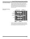
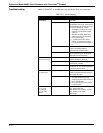
NOTES
1. The instrument must be in Manual or OutofService mode to set the
status option.
2. The AI block only supports the BAD if Limited option. Unsupported
options are not grayed out; they appear on the screen in the same
manner as supported options.
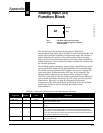
Advanced Features The AI function block provided with Fisher-Rosemount fieldbus devices
provides added capability through the addition of the following
parameters:
ALARM_TYPE – Allows one or more of the process alarm conditions
detected by the AI function block to be used in setting its OUT_D
parameter.
OUT_D – Discrete output of the AI function block based on the
detection of process alarm condition(s). This parameter may be linked
to other function blocks that require a discrete input based on the
detected alarm condition.
VAR_SCAN – Time period in seconds over which the variability index
(VAR_INDEX) is computed.
VAR_INDEX – Process variability index measured as the integral of
average absolute error between PV and its mean value over the
previous evaluation period. This index is calculated as a percent of OUT
span and is updated at the end of the time period defined by
VAR_SCAN.
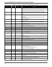
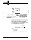
Application Information The configuration of the AI function block and its associated output
channels depends on the specific application. A typical configuration for
the AI block involves the following parameters:
CHANNEL If the device supports more than one measurement,
verify that the selected channel contains the
appropriate measurement or derived value.
L_TYPE Select Direct when the measurement is already in the
engineering units that you want for the block output.
Select Indirect when you want to convert the measured
variable into another, for example, pressure into level
or flow into energy.
Select Indirect Square Root when the block I/O
parameter value represents a flow measurement made
using differential pressure, and when square root
extraction is not performed by the transducer.
SCALING XD_SCALE provides the range and units of the
measurement and OUT_SCALE provides the range
and engineering units of the output.
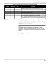
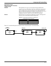
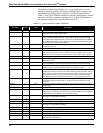
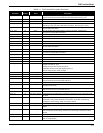
Application Example:
Temperature Transmitter
Situation A temperature transmitter with a range of –200 to 450 °C.
Solution Table B-3 lists the appropriate configuration settings, and Figure B-3
illustrates the correct function block configuration.