


2-9
Installation
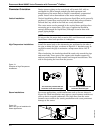
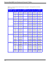
Flanged-Style
Flowmeter Mounting
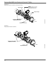
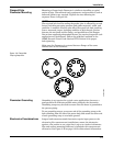
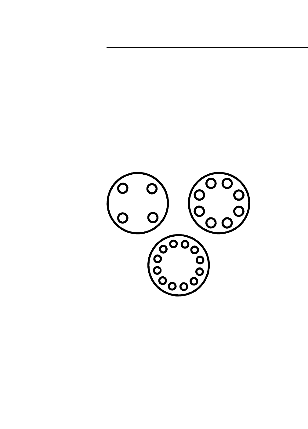
Mounting a flanged-style flowmeter is similar to installing a typical
section of pipe. Conventional tools, equipment, and accessories (such as
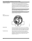
bolts and gaskets) are required. Tighten the nuts following the
sequence shown in Figure 2-8.
NOTES
The required bolt load for sealing the gasket joint is affected by several
factors, including operating pressure and gasket material, width, and
condition. A number of factors also affect the actual bolt load resulting
from a measured torque, including condition of bolt threads, friction
between the nut head and the flange, and parallelism of the flanges.
Due to these application-dependent factors, the required torque for each
application may be different. Follow the guidelines outlined in the
ASME Pressure Vessel Code (Section VIII, Division 2) for proper
bolt tightening.
Make sure the flowmeter is centered between flanges of the same
nominal size as the flowmeter.
Figure 2-8. Flange Bolt
Torquing Sequence.
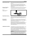
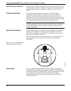
Flowmeter Grounding Grounding is not required in typical vortex applications; however, a
good ground will eliminate possible noise pickup by the electronics.
Grounding straps may be used to ensure that the meter is grounded to
the process piping.
To use grounding straps, secure one end of the grounding strap to the
bolt extending from the side of the meter body and attach the other end
of each grounding strap to a suitable ground.
Electronics Considerations Integral and remote-mounted electronics require input power at the
electronics. For remote-mount installations, mount the electronics
against a flat surface or on a pipe that is up to two inches in diameter.
Pipe and surface-mounting hardware is included with remote-mount
electronics. See Figure 2-16 on page 2-18 for dimensional information.
1
3
2
4
1
5
3
7
2
6
4
8
1
5
9
3
7
11
2
6
10
4
8
12
8800-0088A
4-Bolt
12-Bolt
8-Bolt