


Rosemount Model 8800C Vortex Flowmeter with FOUNDATION
TM
Fieldbus
B-2
BLOCK_ALM 21 None The block alarm is used for all configuration, hardware, connection failure or system
problems in the block. The cause of the alert is entered in the subcode field. The first
alert to become active will set the Active status in the Status parameter. As soon as
the Unreported status is cleared by the alert reporting task, another block alert may
be reported without clearing the Active status, if the subcode has changed.
BLOCK_ERR 06 None This parameter reflects the error status associated with the hardware or software
components associated with a block. It is a bit string, so that multiple errors may be
shown.
CHANNEL 15 None The CHANNEL value is used to select the measurement value. Refer to the
appropriate device manual for information about the specific channels available in
each device.
You must configure the CHANNEL parameter before you can configure the
XD_SCALE parameter.
FIELD_VAL 19 Percent The value and status from the transducer block or from the simulated input when
simulation is enabled.
GRANT_DENY 12 None Options for controlling access of host computers and local control panels to
operating, tuning, and alarm parameters of the block. Not used by device.
HI_ALM 34 None The HI alarm data, which includes a value of the alarm, a timestamp of occurrence
and the state of the alarm.
HI_HI_ALM 33 None The HI HI alarm data, which includes a value of the alarm, a timestamp of
occurrence and the state of the alarm.
HI_HI_LIM 26 EU of PV_SCALE The setting for the alarm limit used to detect the HI HI alarm condition.
HI_HI_PRI 25 None The priority of the HI HI alarm.
HI_LIM 28 EU of PV_SCALE The setting for the alarm limit used to detect the HI alarm condition.
HI_PRI 27 None The priority of the HI alarm.
IO_OPTS 13 None Allows the selection of input/output options used to alter the PV. Low cutoff enabled
is the only selectable option.
L_TYPE 16 None Linearization type. Determines whether the field value is used directly (Direct), is
converted linearly (Indirect), or is converted with the square root (Indirect Square
Root).
LO_ALM 35 None The LO alarm data, which includes a value of the alarm, a timestamp of occurrence
and the state of the alarm.
LO_LIM 30 EU of PV_SCALE The setting for the alarm limit used to detect the LO alarm condition.
LO_LO_ALM 36 None The LO LO alarm data, which includes a value of the alarm, a timestamp of
occurrence and the state of the alarm.
LO_LO_LIM 32 EU of PV_SCALE The setting for the alarm limit used to detect the LO LO alarm condition.
LO_LO_PRI 31 None The priority of the LO LO alarm.
LO_PRI 29 None The priority of the LO alarm.
LOW_CUT 17 % If percentage value of transducer input fails below this, PV = 0.
MODE_BLK 05 None The actual, target, permitted, and normal modes of the block.
Target: The mode to “go to”
Actual: The mode the “block is currently in”
Permitted: Allowed modes that target may take on
Normal: Most common mode for target
OUT 08 EU of OUT_SCALE The block output value and status.
OUT_D 37 None Discrete output to indicate a selected alarm condition.
OUT_SCALE 11 None The high and low scale values, engineering units code, and number of digits to the
right of the decimal point associated with OUT.
PV 07 EU of XD_SCALE The process variable used in block execution.
PV_FTIME 18 Seconds The time constant of the first-order PV filter. It is the time required for a 63% change
in the IN value.
SIMULATE 09 None A group of data that contains the current transducer value and status, the simulated
transducer value and status, and the enable/disable bit.
STRATEGY 03 None The strategy field can be used to identify grouping of blocks. This data is not
checked or processed by the block.
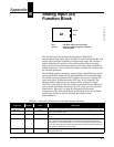
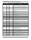
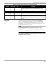
TABLE B-1. Definitions of Analog Input Function Block System Parameters.
Parameter
Index
Number
Units Description